Image filter end terminations
| Linear analog electronic filters |
|---|
Filters designed using the image impedance methodology suffer from a peculiar flaw in the theory. The predicted characteristics of the filter are calculated assuming that the filter is terminated with its own image impedances at each end. This will not usually be the case; the filter will be terminated with fixed resistances. This causes the filter response to deviate from the theoretical. This article explains how the effects of image filter end terminations can be taken into account.
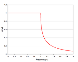
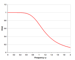
Generally, the effect of the terminations is to cause a rounding of the frequency response at cut-off. The image method predicts a sharp discontinuity in the slope of the response at cut-off which is not realised in practice, although a well designed image filter may get close to this. Another prediction of the image method is zero loss in the passband (assuming ideal lossless components). Again, this cannot be achieved in practice because reflections from the end terminations always cause some loss.
- Parts of this article or section rely on the reader's knowledge of the complex impedance representation of capacitors and inductors and on knowledge of the frequency domain representation of signals.
Symbols used in this article
[edit]Impedances
[edit]- the image impedance at end 1
- the image impedance at end 2
- the image impedance when both ends are identical
- the terminating resistance at end 1
- the terminating resistance at end 2
- the terminating resistance when both ends are identical
Coefficients
[edit]- the reflection coefficient at end 1
- the reflection coefficient at end 2
- the reflection coefficient when both ends are identical
- the transmission coefficient at end 1
- the transmission coefficient at end 2
- the complex propagation coefficient of the filter
- the attenuation coefficient of the filter
- the phase coefficient of the filter
Note that all of these coefficients are defined relative to the image impedance and not the actual input impedance of the filter.
General case
[edit]
The transfer function of any filter connected as shown in the diagram above is given by the expression
where
Note that Vi is the nominal voltage that would be delivered by the generator if it were terminated in its characteristic impedance (i.e. R1), not the actual voltage appearing at the input terminals of the filter.
It can further be noted that the first part of the expression,
- ,
is the same as the expression for the transfer function without taking into account the end terminations. The second part of the expression is thus that part of the response caused by the mismatched impedances;
Symmetrical case
[edit]Where the filter has symmetrical image impedances and terminations, the expression can be considerably reduced. Note that there is no requirement for the filter to be symmetrical internally, only that the end sections have the same image impedance facing into identical terminating impedances.
A further simplification can be made if there are no resistive losses in the filter (or they are assumed to be negligible). In this case, the image impedance is purely real (RI) in the passband and purely imaginary (iXI) in the stopband. The magnitude of the transfer function is given by
where for the passband,
and for the stopband,
Antimetrical case
[edit]A similar simplification can be made for lossless antimetrical filters. In this case the substitution
is made into the general equation. For the passband,
and for the stopband,
Antimetrical, in this context, means that the filter image impedances and terminations at each end are the dual of each other. This will be the case if the filter has a series and shunt section of the same type, respectively, at each end. Symmetrical filters have an even number of half-sections and antimetrical filters have an odd number of half-sections. In the vast majority of cases the filter design will be either symmetrical or antimetrical and one of these reduced expressions will apply.
Some example response plots
[edit] |
 |
 |
See also
[edit]- Image impedance
- Composite image filter
- Dual impedance
- Prototype filter
- Category:Image impedance filters
References
[edit]- Matthaei, Young, Jones Microwave Filters, Impedance-Matching Networks, and Coupling Structures, pp68-72, McGraw-Hill 1964.


![{\displaystyle A(i\omega )={\frac {V_{o}}{V_{i}}}={\sqrt {\frac {Z_{I2}}{Z_{I1}}}}e^{-\gamma }\left[{\frac {\tau _{I1}\tau _{I2}}{1-e^{-2\gamma }r_{I1}r_{I2}}}\right]}](https://wikimedia.org/api/rest_v1/media/math/render/svg/76e9302e29805bb2b4de91543363bec086456af8)


![{\displaystyle \left[{\frac {\tau _{I1}\tau _{I2}}{1-e^{-2\gamma }r_{I1}r_{I2}}}\right].}](https://wikimedia.org/api/rest_v1/media/math/render/svg/5eb12bcf02ede759fe0c646265e8453160f35cb1)
![{\displaystyle A(i\omega )=e^{-\gamma }\left[{\frac {4Z_{I}R}{(R+Z_{I})^{2}-e^{-2\gamma }(R-Z_{I})^{2}}}\right]}](https://wikimedia.org/api/rest_v1/media/math/render/svg/226a60fe1eb49709c78075721166bfb46495868c)


