Диодный мост
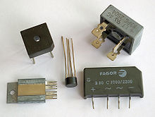
 Диодный мост в различных пакетах | |
| Тип | Полупроводник |
|---|---|
| Изобретенный | Карол Поллак в 1895 году |
| Электронный символ | |
 2 входы с чередующимися (AC) преобразованы в 2 с прямым током (DC) выходы | |

Диодный мост - это мостовая схема выпрямителя из четырех диодов , которая используется в процессе преобразования переменного тока (AC) из входных клемм в постоянный ток (DC, IE Фиксированная полярность ) на выходных клеммах. Его функция состоит в том, чтобы преобразовать отрицательные части напряжения формы волны переменного тока в положительное напряжение, после чего можно использовать фильтр низкого уровня для сглаживания результата в DC. [ 1 ]
При использовании в наиболее распространенном приложении для преобразования входа в выходной точке (AC) в выходной (DC) вывод известен как выпрямитель моста . моста Выпрямитель обеспечивает полную волну выпрямления с двухпроходного входа переменного тока, что приводит к снижению стоимости и веса по сравнению с выпрямителем с трехпроводным входом от трансформатора с вторичной обмоткой в центре . [ 2 ]
До наличия интегрированных схем был построен выпрямитель моста из отдельных диодов. Примерно с 1950 года был доступен единственный четырехместный компонент, содержащий четыре диода, подключенные в конфигурации моста и теперь доступен с различными напряжения рейтингами и тока.
Диоды также используются в топологиях моста вместе с конденсаторами в качестве множителей напряжений .
История
[ редактировать ]Диодная мостовая трасса была изобретена Каролом Поллаком и запатентованным в декабре 1895 года в Великобритании [ 3 ] и в январе 1896 года в Германии. [ 4 ] [ 5 ] В 1897 году Лео Грец независимо изобрел и опубликовал аналогичную схему. [ 6 ] [ 7 ] Сегодня схема иногда называют «схемой Graetz» или «мост Graetz». [ 8 ]
Ток поток
[ редактировать ]Согласно традиционной модели текущего потока , первоначально созданной Бенджамином Франклина и по -прежнему сопровождается большинством инженеров сегодня [ 9 ] ), ток течет через электрические проводники от положительного до отрицательного полюса (определяется как положительный поток). На самом деле свободные электроны в проводнике почти всегда переходят от негативного к положительному полюсу. Однако в подавляющем большинстве приложений фактическое направление потока тока не имеет значения. Поэтому в обсуждении ниже обычной модели сохраняется.
The fundamental characteristic of a diode is that current can flow only one way through it, which is defined as the forward direction. A diode bridge uses diodes as series components to allow current to pass in the forward direction during the positive part of the AC cycle and as shunt components to redirect current flowing in the reverse direction during the negative part of the AC cycle to the opposite rails.
Rectifier
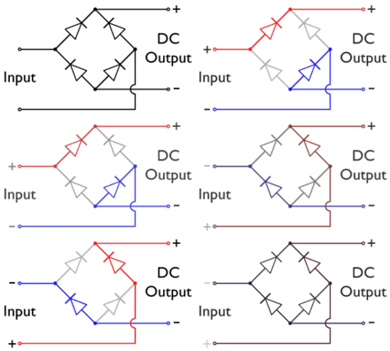
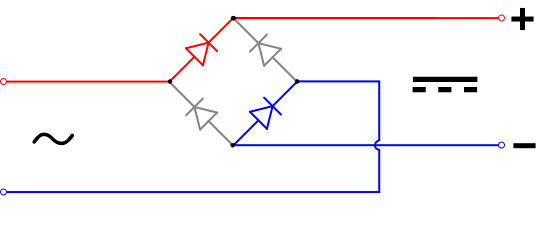
[edit]In the diagrams below, when the input connected to the left corner of the diamond is positive, and the input connected to the right corner is negative, current flows from the upper supply terminal to the right along the red (positive) path to the output and returns to the lower supply terminal through the blue (negative) path.
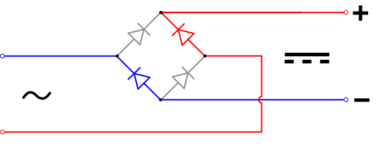
When the input connected to the left corner is negative, and the input connected to the right corner is positive, current flows from the lower supply terminal to the right along the red (positive) path to the output and returns to the upper supply terminal through the blue (negative) path.[10]

In each case, the upper right output remains positive,[11] and lower right output negative. Since this is true whether the input is AC or DC, this circuit not only produces a DC output from an AC input, it can also provide reverse-polarity protection; that is, it permits normal functioning of DC-powered equipment when batteries have been installed backwards, or when the leads from a DC power source have been reversed, and protects the equipment from potential damage caused by reverse polarity.[12]
Alternatives to the diode-bridge full-wave rectifiers are the center-tapped transformer and double-diode rectifier, and voltage doubler rectifier using two diodes and two capacitors in a bridge topology.

Smoothing circuits
[edit]With AC input, the output of a diode bridge (called a full-wave rectifier for this purpose; there is also half-wave rectification, which does not use a diode bridge) is polarized pulsating non-sinusoidal voltage of the same amplitude but twice the frequency of the input. It may be considered as DC voltage upon which is superimposed a very large ripple voltage. This kind of electric power is not very usable, because ripple is dissipated as waste heat in DC circuit components and may cause noise or distortion during circuit operation. So nearly all rectifiers are followed by a series of bandpass or bandstop filters and/or a voltage regulator to convert most or all of the ripple voltage into a smoother and possibly higher DC output. A filter may be as simple as a single sufficiently large capacitor or choke, but most power-supply filters have multiple alternating series and shunt components. When the ripple voltage rises, reactive power is stored in the filter components, reducing the voltage; when the ripple voltage falls, reactive power is discharged from the filter components, raising the voltage. The final stage of rectification may consist of a zener diode-based voltage regulator, which almost completely eliminates any residual ripple.
Polyphase diode bridges
[edit]The diode bridge can be generalized to rectify polyphase AC inputs. For example, for a three-phase AC input, a half-wave rectifier consists of three diodes, but a full-wave bridge rectifier consists of six diodes.[citation needed]
A half-wave rectifier may be considered a wye connection (star connection), because it returns the current through the center (neutral) wire. A full-wave rectifier is more like a delta connection, although it can be connected to the three-phase source of either wye or delta and it does not use the center (neutral) wire.[citation needed]


See also
[edit]- 1N400x general-purpose diodes also called rectifier diodes
- Active rectification
- HVDC converter
References
[edit]- ^ Yazdani, Amirnaser; Iravani, Reza (15 February 2010). Voltage-Sourced Converters in Power Systems Modeling, Control, and Applications. Willey. ISBN 9780470521564.
- ^ Horowitz, Paul; Hill, Winfield (1989). The Art of Electronics (Second ed.). Cambridge University Press. pp. 44–47. ISBN 0-521-37095-7.
- ^ British patent 24398.
- ^ (Graetz, 1897), p. 327 footnote.
- ^ (Editorial staff) (24 June 1897). "Ein neues Gleichrichter-Verfahren" [A new method of rectification]. Elektrotechnische Zeitschrift (in German). 18 (25): 359 and footnote.
- ^ See:
- Graetz, L. (1 May 1897). "Electrochemisches Verfahren, um Wechselströme in Gleichströme zu verwandeln" [Electrochemical method of changing alternating into direct currents]. Sitzungsberichte der Mathematisch-Physikalischen Classe der Königlich Bayerischen Akademie der Wissenschaften zu München (Transactions of the Mathematical-Physical Classes of the Royal Bavarian Academy of Sciences in Munich) (in German). 27 (10): 223–228. Bibcode:1897AnP...298..323G. doi:10.1002/andp.18972981008.
- Graetz, L. (1897). "Electrochemisches Verfahren, um Wechselströme in Gleichströme zu verwandeln" [Electrochemical method of changing alternating into direct currents]. Annalen der Physik und Chemie. 3rd series (in German). 62 (10): 323–327. Bibcode:1897AnP...298..323G. doi:10.1002/andp.18972981008.
- Graetz, L. (22 July 1897). "Electrochemisches Verfahren, um Wechselströme in Gleichströme zu verwandeln" [Electrochemical method of changing alternating into direct currents]. Elektrotechnische Zeitschrift (in German). 18 (29): 423–424. Bibcode:1897AnP...298..323G. doi:10.1002/andp.18972981008.
- ^ Strzelecki, Ryszard Michal; Benysek, Grzegorz, eds. (August 29, 2008). Power Electronics in Smart Electrical Energy Networks. Springer. p. 57. ISBN 9781848003187.
- ^ "Graetz Flow Control Circuit". Archived from the original on 2013-11-04.
- ^ Stutz, Michael ([email protected]), "Conventional versus electron flow", All About Circuits, Vol. 1, Chapter 1, 2000.
- ^ Sears, Francis W.; Zemansky, Mark W.; Young, Hugh D., eds. (1982). University Physics (6th ed.). Addison-Wesely Publishing Co., Inc. p. 685. ISBN 0201071959.
- ^ "Bridge Rectifier Circuit - Electronics Basics". The Geek Pub. 15 August 2019. Retrieved 3 September 2019.
- ^ "Reverse Polarity Protection". The Renewable Energy UK Website. Bridge Rectifier for Reverse Polarity Protection. Archived from the original on 4 May 2023. Retrieved 18 December 2023.
- ^ "Rectifier", Concise Encyclopedia of Science and Technology, Third Edition, Sybil P. Parker, ed. McGraw-Hill, Inc., 1994, p. 1589.

