Паровой локомотив
Эта статья требует дополнительных цитат для проверки . ( ноябрь 2021 г. ) |


Паровый локомотив - это локомотив , который обеспечивает силу перемещаться само по себе и другие транспортные средства посредством расширения пара . [ 1 ] : 80 Он подпитывается сжиганием горючего материала (обычно угля , нефть или, редко, древесина локомотива ), чтобы нагреть воду в котле до точки, где он становится газообразным, а его объем увеличивается 1700 раз. Функционально, это паровой двигатель на колесах. [ 2 ]
В большинстве локомотивов пар поочередно признается на каждом конце своих цилиндров , в которых поршни механически соединены с основными колесами локомотива. Топливо и водоснабжение обычно переносятся с локомотивом, либо на самом локомотиве, либо в нежной в сочетании с ним. Изменения в этой общей конструкции включают котлы с электрическим питанием, турбины вместо поршней и использование пара, генерируемого внешним.
Steam locomotives were first developed in the United Kingdom during the early 19th century and used for railway transport until the middle of the 20th century. Richard Trevithick built the first steam locomotive known to have hauled a load over a distance at Pen-y-darren in 1804, although he produced an earlier locomotive for trial at Coalbrookdale in 1802.[3] Salamanca, built in 1812 by Matthew Murray for the Middleton Railway, was the first commercially successful steam locomotive.[4] Locomotion No. 1, built by George Stephenson and his son Robert's company Robert Stephenson and Company, was the first steam locomotive to haul passengers on a public railway, the Stockton and Darlington Railway, in 1825. Rapid development ensued; in 1830 George Stephenson opened the first public inter-city railway, the Liverpool and Manchester Railway, after the success of Rocket at the 1829 Rainhill Trials had proved that steam locomotives could perform such duties. Robert Stephenson and Company was the pre-eminent builder of steam locomotives in the first decades of steam for railways in the United Kingdom, the United States, and much of Europe.[5]
Towards the end of the steam era, a longstanding British emphasis on speed culminated in a record, still unbroken, of 126 miles per hour (203 kilometres per hour) by LNER Class A4 4468 Mallard,[6] however there are long-standing claims that the Pennsylvania Railroad class S1 achieved speeds upwards of 150 mph, though this was never officially proven.[7][8][9][10] In the United States, larger loading gauges allowed the development of very large, heavy locomotives such as the Union Pacific Big Boy, which weighs 540 long tons (550 t; 600 short tons) and has a tractive effort of 135,375 pounds-force (602,180 newtons).[11][note 1]
Beginning in the early 1900s, steam locomotives were gradually superseded by electric and diesel locomotives, with railways fully converting to electric and diesel power beginning in the late 1930s. The majority of steam locomotives were retired from regular service by the 1980s, although several continue to run on tourist and heritage lines.[12]
History
[edit]Britain
[edit]The earliest railways employed horses to draw carts along rail tracks.[13] In 1784, William Murdoch, a Scottish inventor, built a small-scale prototype of a steam road locomotive in Birmingham.[14][15] A full-scale rail steam locomotive was proposed by William Reynolds around 1787.[16] An early working model of a steam rail locomotive was designed and constructed by steamboat pioneer John Fitch in the US during 1794.[17] Some sources claim Fitch's model was operable already by the 1780s and that he demonstrated his locomotive to George Washington.[18] His steam locomotive used interior bladed wheels guided by rails or tracks. The model still exists at the Ohio Historical Society Museum in Columbus, US.[19] The authenticity and date of this locomotive is disputed by some experts and a workable steam train would have to await the invention of the high-pressure steam engine by Richard Trevithick, who pioneered the use of steam locomotives.[20]

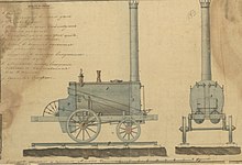
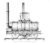
The first full-scale working railway steam locomotive was the 3 ft (914 mm) gauge Coalbrookdale Locomotive built by Trevithick in 1802. It was constructed for the Coalbrookdale ironworks in Shropshire in the United Kingdom though no record of it working there has survived.[21] On 21 February 1804, the first recorded steam-hauled railway journey took place as another of Trevithick's locomotives hauled a train along the 4 ft 4 in (1,321 mm)-wide tramway from the Pen-y-darren ironworks, near Merthyr Tydfil, to Abercynon in South Wales.[22][23] Accompanied by Andrew Vivian, it ran with mixed success.[24] The design incorporated a number of important innovations that included using high-pressure steam which reduced the weight of the engine and increased its efficiency.
Trevithick visited the Newcastle area in 1804 and had a ready audience of colliery (coal mine) owners and engineers. The visit was so successful that the colliery railways in north-east England became the leading centre for experimentation and development of the steam locomotive.[25] Trevithick continued his own steam propulsion experiments through another trio of locomotives, concluding with the Catch Me Who Can in 1808, first in the world to haul fare-paying passengers.


In 1812, Matthew Murray's successful twin-cylinder rack locomotive Salamanca first ran on the edge-railed rack-and-pinion Middleton Railway.[26] Another well-known early locomotive was Puffing Billy, built 1813–14 by engineer William Hedley. It was intended to work on the Wylam Colliery near Newcastle upon Tyne. This locomotive is the oldest preserved, and is on static display at the Science Museum, London.
George Stephenson
[edit]George Stephenson, a former miner working as an engine-wright at Killingworth Colliery, developed up to sixteen Killingworth locomotives, including Blücher in 1814, another in 1815, and a (newly identified) Killingworth Billy in 1816. He also constructed The Duke in 1817 for the Kilmarnock and Troon Railway, which was the first steam locomotive to work in Scotland.
In 1825, Stephenson built Locomotion No. 1 for the Stockton and Darlington Railway, north-east England, which was the first public steam railway in the world. In 1829, his son Robert built in Newcastle The Rocket, which was entered in and won the Rainhill Trials. This success led to the company emerging as the pre-eminent builder of steam locomotives used on railways in the UK, US and much of Europe.[27] The Liverpool and Manchester Railway opened a year later making exclusive use of steam power for passenger and goods trains.
United States
[edit]
Before the arrival of British imports, some domestic steam locomotive prototypes were built and tested in the United States, including John Fitch's miniature prototype. A prominent full sized example was Col. John Steven's "steam wagon" which was demonstrated on a loop of track in Hoboken, New Jersey in 1825.[28]
Many of the earliest locomotives for commercial use on American railroads were imported from Great Britain, including first the Stourbridge Lion and later the John Bull. However, a domestic locomotive-manufacturing industry was soon established. In 1830, the Baltimore and Ohio Railroad's Tom Thumb, designed by Peter Cooper,[29] was the first commercial US-built locomotive to run in America; it was intended as a demonstration of the potential of steam traction rather than as a revenue-earning locomotive. The DeWitt Clinton, built in 1831 for the Mohawk and Hudson Railroad, was a notable early locomotive.[27][30]
As of 2021[update], the original John Bull was on static display in the National Museum of American History in Washington, D.C.[31] The replica is preserved at the Railroad Museum of Pennsylvania.[32]
Continental Europe
[edit]
The first railway service outside the United Kingdom and North America was opened in 1829 in France between Saint-Etienne and Lyon; it was initially limited to animal traction and converted to steam traction early 1831, using Seguin locomotives. The first steam locomotive in service in Europe outside of France was named The Elephant, which on 5 May 1835 hauled a train on the first line in Belgium, linking Mechelen and Brussels.

In Germany, the first working steam locomotive was a rack-and-pinion engine, similar to the Salamanca, designed by the British locomotive pioneer John Blenkinsop. Built in June 1816 by Johann Friedrich Krigar in the Royal Berlin Iron Foundry (Königliche Eisengießerei zu Berlin), the locomotive ran on a circular track in the factory yard. It was the first locomotive to be built on the European mainland and the first steam-powered passenger service; curious onlookers could ride in the attached coaches for a fee. It is portrayed on a New Year's badge for the Royal Foundry dated 1816. Another locomotive was built using the same system in 1817. They were to be used on pit railways in Königshütte and in Luisenthal on the Saar (today part of Völklingen), but neither could be returned to working order after being dismantled, moved and reassembled. On 7 December 1835, the Adler ran for the first time between Nuremberg and Fürth on the Bavarian Ludwig Railway. It was the 118th engine from the locomotive works of Robert Stephenson and stood under patent protection.
In Russia, the first steam locomotive was built in 1834 by Cherepanovs, however, it suffered from the lack of coal in the area and was replaced with horse traction after all the woods nearby had been cut down. The first Russian Tsarskoye Selo steam railway started in 1837 with locomotives purchased from Robert Stephenson and Company.
In 1837, the first steam railway started in Austria on the Emperor Ferdinand Northern Railway between Vienna-Floridsdorf and Deutsch-Wagram. The oldest continually working steam engine in the world also runs in Austria: the GKB 671 built in 1860, has never been taken out of service, and is still used for special excursions.
In 1838, the third steam locomotive to be built in Germany, the Saxonia, was manufactured by the Maschinenbaufirma Übigau near Dresden, built by Prof. Johann Andreas Schubert. The first independently designed locomotive in Germany was the Beuth, built by August Borsig in 1841. The first locomotive produced by Henschel-Werke in Kassel, the Drache, was delivered in 1848.
The first steam locomotives operating in Italy were the Bayard and the Vesuvio, running on the Napoli-Portici line, in the Kingdom of the Two Sicilies.
The first railway line over Swiss territory was the Strasbourg–Basel line opened in 1844. Three years later, in 1847, the first fully Swiss railway line, the Spanisch Brötli Bahn, from Zürich to Baden was opened.
Australia
[edit]The arid nature of south Australia posed distinctive challenges to their early steam locomotion network. The high concentration of magnesium chloride in the well water (bore water) used in locomotive boilers on the Trans-Australian Railway caused serious and expensive maintenance problems. At no point along its route does the line cross a permanent freshwater watercourse, so bore water had to be relied on. No inexpensive treatment for the highly mineralised water was available, and locomotive boilers were lasting less than a quarter of the time normally expected.[33] In the days of steam locomotion, about half the total train load was water for the engine. The line's operator, Commonwealth Railways, was an early adopter of the diesel-electric locomotive.
Components
[edit]
| Key to numbered components |
|---|
Boiler
[edit]The fire-tube boiler was standard practice for steam locomotive.[why?] Although other types of boiler were evaluated they were not widely used, except for some 1,000 locomotives in Hungary which used the water-tube Brotan boiler.[citation needed]

A boiler consists of a firebox where the fuel is burned, a barrel where water is turned into steam, and a smokebox which is kept at a slightly lower pressure than outside the firebox.
Solid fuel, such as wood, coal or coke, is thrown into the firebox through a door by a fireman, onto a set of grates which hold the fuel in a bed as it burns. Ash falls through the grate into an ashpan. If oil is used as the fuel, a door is needed for adjusting the air flow, maintaining the firebox, and cleaning the oil jets.
The fire-tube boiler has internal tubes connecting the firebox to the smokebox through which the combustion gases flow transferring heat to the water. All the tubes together provide a large contact area, called the tube heating surface, between the gas and water in the boiler. Boiler water surrounds the firebox to stop the metal from becoming too hot. This is another area where the gas transfers heat to the water and is called the firebox heating surface. Ash and char collect in the smokebox as the gas gets drawn up the chimney (stack or smokestack in the US) by the exhaust steam from the cylinders.
The pressure in the boiler has to be monitored using a gauge mounted in the cab. Steam pressure can be released manually by the driver or fireman. If the pressure reaches the boiler's design working limit, a safety valve opens automatically to reduce the pressure[34] and avoid a catastrophic accident.

The exhaust steam from the engine cylinders shoots out of a nozzle pointing up the chimney in the smokebox. The steam entrains or drags the smokebox gases with it which maintains a lower pressure in the smokebox than that under the firebox grate. This pressure difference causes air to flow up through the coal bed and keeps the fire burning.
The search for thermal efficiency greater than that of a typical fire-tube boiler led engineers, such as Nigel Gresley, to consider the water-tube boiler. Although he tested the concept on the LNER Class W1, the difficulties during development exceeded the will to increase efficiency by that route.
The steam generated in the boiler not only moves the locomotive, but is also used to operate other devices such as the whistle, the air compressor for the brakes, the pump for replenishing the water in the boiler and the passenger car heating system. The constant demand for steam requires a periodic replacement of water in the boiler. The water is kept in a tank in the locomotive tender or wrapped around the boiler in the case of a tank locomotive. Periodic stops are required to refill the tanks; an alternative was a scoop installed under the tender that collected water as the train passed over a track pan located between the rails.
While the locomotive is producing steam, the amount of water in the boiler is constantly monitored by looking at the water level in a transparent tube, or sight glass. Efficient and safe operation of the boiler requires keeping the level in between lines marked on the sight glass. If the water level is too high, steam production falls, efficiency is lost and water is carried out with the steam into the cylinders, possibly causing mechanical damage. More seriously, if the water level gets too low, the crown sheet (top sheet) of the firebox becomes exposed. Without water on top of the sheet to transfer away the heat of combustion, it softens and fails, letting high-pressure steam into the firebox and the cab. The development of the fusible plug, a temperature-sensitive device, ensured a controlled venting of steam into the firebox to warn the fireman to add water.
Scale builds up in the boiler and prevents adequate heat transfer, and corrosion eventually degrades the boiler materials to the point where it needs to be rebuilt or replaced. Start-up on a large engine may take hours of preliminary heating of the boiler water before sufficient steam is available.
Although the boiler is typically placed horizontally, for locomotives designed to work in locations with steep slopes it may be more appropriate to consider a vertical boiler or one mounted such that the boiler remains horizontal but the wheels are inclined to suit the slope of the rails.
Steam circuit
[edit]This section needs additional citations for verification. (April 2021) |

The steam generated in the boiler fills the space above the water in the partially filled boiler. Its maximum working pressure is limited by spring-loaded safety valves. It is then collected either in a perforated tube fitted above the water level or by a dome that often houses the regulator valve, or throttle, the purpose of which is to control the amount of steam leaving the boiler. The steam then either travels directly along and down a steam pipe to the engine unit or may first pass into the wet header of a superheater, the role of the latter being to improve thermal efficiency and eliminate water droplets suspended in the "saturated steam", the state in which it leaves the boiler. On leaving the superheater, the steam exits the dry header of the superheater and passes down a steam pipe, entering the steam chests adjacent to the cylinders of a reciprocating engine. Inside each steam chest is a sliding valve that distributes the steam via ports that connect the steam chest to the ends of the cylinder space. The role of the valves is twofold: admission of each fresh dose of steam, and exhaust of the used steam once it has done its work.
The cylinders are double-acting, with steam admitted to each side of the piston in turn. In a two-cylinder locomotive, one cylinder is located on each side of the vehicle. The cranks are set 90° out of phase. During a full rotation of the driving wheel, steam provides four power strokes; each cylinder receives two injections of steam per revolution. The first stroke is to the front of the piston and the second stroke to the rear of the piston; hence two working strokes. Consequently, two deliveries of steam onto each piston face in the two cylinders generates a full revolution of the driving wheel. Each piston is attached to the driving axle on each side by a connecting rod, and the driving wheels are connected together by coupling rods to transmit power from the main driver to the other wheels. Note that at the two "dead centres", when the connecting rod is on the same axis as the crankpin on the driving wheel, the connecting rod applies no torque to the wheel. Therefore, if both cranksets could be at "dead centre" at the same time, and the wheels should happen to stop in this position, the locomotive could not start moving. Therefore, the crankpins are attached to the wheels at a 90° angle to each other, so only one side can be at dead centre at a time.
Each piston transmits power through a crosshead, connecting rod (Main rod in the US) and a crankpin on the driving wheel (Main driver in the US) or to a crank on a driving axle. The movement of the valves in the steam chest is controlled through a set of rods and linkages called the valve gear, actuated from the driving axle or from the crankpin; the valve gear includes devices that allow reversing the engine, adjusting valve travel and the timing of the admission and exhaust events. The cut-off point determines the moment when the valve blocks a steam port, "cutting off" admission steam and thus determining the proportion of the stroke during which steam is admitted into the cylinder; for example a 50% cut-off admits steam for half the stroke of the piston. The remainder of the stroke is driven by the expansive force of the steam. Careful use of cut-off provides economical use of steam and in turn, reduces fuel and water consumption. The reversing lever (Johnson bar in the US), or screw-reverser (if so equipped), that controls the cut-off, therefore, performs a similar function to a gearshift in an automobile – maximum cut-off, providing maximum tractive effort at the expense of efficiency, is used to pull away from a standing start, whilst a cut-off as low as 10% is used when cruising, providing reduced tractive effort, and therefore lower fuel/water consumption.[35]
Exhaust steam is directed upwards out of the locomotive through the chimney, by way of a nozzle called a blastpipe, creating the familiar "chuffing" sound of the steam locomotive. The blastpipe is placed at a strategic point inside the smokebox that is at the same time traversed by the combustion gases drawn through the boiler and grate by the action of the steam blast. The combining of the two streams, steam and exhaust gases, is crucial to the efficiency of any steam locomotive, and the internal profiles of the chimney (or, strictly speaking, the ejector) require careful design and adjustment. This has been the object of intensive studies by a number of engineers (and often ignored by others, sometimes with catastrophic consequences). The fact that the draught depends on the exhaust pressure means that power delivery and power generation are automatically self-adjusting. Among other things, a balance has to be struck between obtaining sufficient draught for combustion whilst giving the exhaust gases and particles sufficient time to be consumed. In the past, a strong draught could lift the fire off the grate, or cause the ejection of unburnt particles of fuel, dirt and pollution for which steam locomotives had an unenviable reputation. Moreover, the pumping action of the exhaust has the counter-effect of exerting back pressure on the side of the piston receiving steam, thus slightly reducing cylinder power. Designing the exhaust ejector became a specific science, with engineers such as Chapelon, Giesl and Porta making large improvements in thermal efficiency and a significant reduction in maintenance time[36] and pollution.[37] A similar system was used by some early gasoline/kerosene tractor manufacturers (Advance-Rumely/Hart-Parr) – the exhaust gas volume was vented through a cooling tower, allowing the steam exhaust to draw more air past the radiator.
Running gear
[edit]


Running gear includes the brake gear, wheel sets, axleboxes, springing and the motion that includes connecting rods and valve gear. The transmission of the power from the pistons to the rails and the behaviour of the locomotive as a vehicle, being able to negotiate curves, points and irregularities in the track, is of paramount importance. Because reciprocating power has to be directly applied to the rail from 0 rpm upwards, this creates the problem of adhesion of the driving wheels to the smooth rail surface. Adhesive weight is the portion of the locomotive's weight bearing on the driving wheels. This is made more effective if a pair of driving wheels is able to make the most of its axle load, i.e. its individual share of the adhesive weight. Equalising beams connecting the ends of leaf springs have often been deemed a complication in Britain, however, locomotives fitted with the beams have usually been less prone to loss of traction due to wheel-slip. Suspension using equalizing levers between driving axles, and between driving axles and trucks, was standard practice on North American locomotives to maintain even wheel loads when operating on uneven track.
Locomotives with total adhesion, where all of the wheels are coupled together, generally lack stability at speed. To counter this, locomotives often fit unpowered carrying wheels mounted on two-wheeled trucks or four-wheeled bogies centred by springs/inverted rockers/geared rollers that help to guide the locomotive through curves. These usually take on weight – of the cylinders at the front or the firebox at the rear – when the width exceeds that of the mainframes. Locomotives with multiple coupled-wheels on a rigid chassis would have unacceptable flange forces on tight curves giving excessive flange and rail wear, track spreading and wheel climb derailments. One solution was to remove or thin the flanges on an axle. More common was to give axles end-play and use lateral motion control with spring or inclined-plane gravity devices.
Railroads generally preferred locomotives with fewer axles, to reduce maintenance costs. The number of axles required was dictated by the maximum axle loading of the railroad in question. A builder would typically add axles until the maximum weight on any one axle was acceptable to the railroad's maximum axle loading. A locomotive with a wheel arrangement of two lead axles, two drive axles, and one trailing axle was a high-speed machine. Two lead axles were necessary to have good tracking at high speeds. Two drive axles had a lower reciprocating mass than three, four, five or six coupled axles. They were thus able to turn at very high speeds due to the lower reciprocating mass. A trailing axle was able to support a huge firebox, hence most locomotives with the wheel arrangement of 4-4-2 (American Type Atlantic) were called free steamers and were able to maintain steam pressure regardless of throttle setting.
Chassis
[edit]The chassis, or locomotive frame, is the principal structure onto which the boiler is mounted and which incorporates the various elements of the running gear. The boiler is rigidly mounted on a "saddle" beneath the smokebox and in front of the boiler barrel, but the firebox at the rear is allowed to slide forward and backwards, to allow for expansion when hot.
European locomotives usually use "plate frames", where two vertical flat plates form the main chassis, with a variety of spacers and a buffer beam at each end to form a rigid structure. When inside cylinders are mounted between the frames, the plate frames are a single large casting that forms a major support element. The axleboxes slide up and down to give some sprung suspension, against thickened webs attached to the frame, called "hornblocks".[38]
American practice for many years was to use built-up bar frames, with the smokebox saddle/cylinder structure and drag beam integrated therein. In the 1920s, with the introduction of "superpower", the cast-steel locomotive bed became the norm, incorporating frames, spring hangers, motion brackets, smokebox saddle and cylinder blocks into a single complex, sturdy but heavy casting. A SNCF design study using welded tubular frames gave a rigid frame with a 30% weight reduction.[39]
Fuel and water
[edit]
Generally, the largest locomotives are permanently coupled to a tender that carries the water and fuel. Often, locomotives working shorter distances do not have a tender and carry the fuel in a bunker, with the water carried in tanks placed next to the boiler. The tanks can be in various configurations, including two tanks alongside (side tanks or pannier tanks), one on top (saddle tank) or one between the frames (well tank).
The fuel used depended on what was economically available to the railway. In the UK and other parts of Europe, plentiful supplies of coal made this the obvious choice from the earliest days of the steam engine. Until 1870,[40] the majority of locomotives in the United States burned wood, but as the Eastern forests were cleared, coal gradually became more widely used until it became the dominant fuel worldwide in steam locomotives. Railways serving sugar cane farming operations burned bagasse, a byproduct of sugar refining. In the US, the ready availability and low price of oil made it a popular steam locomotive fuel after 1900 for the southwestern railroads, particularly the Southern Pacific. In the Australian state of Victoria, many steam locomotives were converted to heavy oil firing after World War II. German, Russian, Australian and British railways experimented with using coal dust to fire locomotives.
During World War 2, a number of Swiss steam shunting locomotives were modified to use electrically heated boilers, consuming around 480 kW of power collected from an overhead line with a pantograph. These locomotives were significantly less efficient than electric ones; they were used because Switzerland was suffering a coal shortage because of the War, but had access to plentiful hydroelectricity.[41]
A number of tourist lines and heritage locomotives in Switzerland, Argentina and Australia have used light diesel-type oil.[42]
Water was supplied at stopping places and locomotive depots from a dedicated water tower connected to water cranes or gantries. In the UK, the US and France, water troughs (track pans in the US) were provided on some main lines to allow locomotives to replenish their water supply without stopping, from rainwater or snowmelt that filled the trough due to inclement weather. This was achieved by using a deployable "water scoop" fitted under the tender or the rear water tank in the case of a large tank engine; the fireman remotely lowered the scoop into the trough, the speed of the engine forced the water up into the tank, and the scoop was raised again once it was full.

Water is essential for the operation of a steam locomotive. As Swengel argued:
It has the highest specific heat of any common substance; that is, more thermal energy is stored by heating water to a given temperature than would be stored by heating an equal mass of steel or copper to the same temperature. In addition, the property of vapourising (forming steam) stores additional energy without increasing the temperature… water is a very satisfactory medium for converting thermal energy of fuel into mechanical energy.[43]
Swengel went on to note that "at low temperature and relatively low boiler outputs", good water and regular boiler washout was an acceptable practice, even though such maintenance was high. As steam pressures increased, however, a problem of "foaming" or "priming" developed in the boiler, wherein dissolved solids in the water formed "tough-skinned bubbles" inside the boiler, which in turn were carried into the steam pipes and could blow off the cylinder heads. To overcome the problem, hot mineral-concentrated water was deliberately wasted (blown down) from the boiler periodically. Higher steam pressures required more blowing-down of water out of the boiler. Oxygen generated by boiling water attacks the boiler, and with increased steam pressure the rate of rust (iron oxide) generated inside the boiler increases. One way to help overcome the problem was water treatment. Swengel suggested that these problems contributed to the interest in electrification of railways.[43]
In the 1970s, L.D. Porta developed a sophisticated system of heavy-duty chemical water treatment (Porta Treatment) that not only keeps the inside of the boiler clean and prevents corrosion, but modifies the foam in such a way as to form a compact "blanket" on the water surface that filters the steam as it is produced, keeping it pure and preventing carry-over into the cylinders of water and suspended abrasive matter.[44][45]
Some steam locomotives have been run on alternative fuels such as used cooking oil like Grand Canyon Railway 4960, Grand Canyon Railway 29, U.S. Sugar 148, and the Disneyland Railroad Locomotives.[46][47][48][49][50][51][52]
Crew
[edit]
A steam locomotive is normally controlled from the boiler's backhead, and the crew is usually protected from the elements by a cab. A crew of at least two people is normally required to operate a steam locomotive. One, the train driver or engineer (North America), is responsible for controlling the locomotive's starting, stopping, and speed, and the fireman is responsible for maintaining the fire, regulating steam pressure and monitoring boiler and tender water levels. Due to the historical loss of operational infrastructure and staffing, preserved steam locomotives operating on the mainline will often have a support crew travelling with the train.
Fittings and appliances
[edit]All locomotives are fitted with a variety of appliances. Some of these relate directly to the operation of the steam engine; others are for signalling, train control or other purposes. In the United States, the Federal Railroad Administration mandated the use of certain appliances over the years in response to safety concerns. The most typical appliances are as follows:
Steam pumps and injectors
[edit]Water (feedwater) must be delivered to the boiler to replace that which is exhausted as steam after delivering a working stroke to the pistons. As the boiler is under pressure during operation, feedwater must be forced into the boiler at a pressure that is greater than the steam pressure, necessitating the use of some sort of pump. Hand-operated pumps sufficed for the very earliest locomotives. Later engines used pumps driven by the motion of the pistons (axle pumps), which were simple to operate, reliable and could handle large quantities of water but only operated when the locomotive was moving and could overload the valve gear and piston rods at high speeds. Steam injectors later replaced the pump, while some engines transitioned to turbopumps. Standard practice evolved to use two independent systems for feeding water to the boiler; either two steam injectors or, on more conservative designs, axle pumps when running at service speed and a steam injector for filling the boiler when stationary or at low speeds. By the 20th century virtually all new-built locomotives used only steam injectors – often one injector was supplied with "live" steam straight from the boiler itself and the other used exhaust steam from the locomotive's cylinders, which was more efficient (since it made use of otherwise wasted steam) but could only be used when the locomotive was in motion and the regulator was open. Injectors became unreliable if the feedwater was at a high temperature, so locomotives with feedwater heaters, tank locomotives with the tanks in contact with the boiler and condensing locomotives sometimes used reciprocating steam pumps or turbopumps.
Vertical glass tubes, known as water gauges or water glasses, show the level of water in the boiler and are carefully monitored at all times while the boiler is being fired. Before the 1870s it was more common to have a series of try-cocks fitted to the boiler within reach of the crew; each try cock (at least two and usually three were fitted) was mounted at a different level. By opening each try-cock and seeing if steam or water vented through it, the level of water in the boiler could be estimated with limited accuracy. As boiler pressures increased the use of try-cocks became increasingly dangerous and the valves were prone to blockage with scale or sediment, giving false readings. This led to their replacement with the sight glass. As with the injectors, two glasses with separate fittings were usually installed to provide independent readings.
Boiler insulation
[edit]The term for pipe and boiler insulation is "lagging"[53] which derives from the cooper's term for a wooden barrel stave.[54] Two of the earliest steam locomotives used wooden lagging to insulate their boilers: the Salamanca, the first commercially successful steam locomotive, built in 1812,[4] and the Locomotion No. 1, the first steam locomotive to carry passengers on a public rail line. Large amounts of heat are wasted if a boiler is not insulated. Early locomotives used lags, shaped wooden staves, fitted lengthways along the boiler barrel, and held in place by hoops, metal bands, the terms and methods are from cooperage.
-
 The Salamanca (1812)
 -
 Locomotion No. 1, (1825)
 -
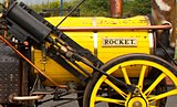 Rocket (1829; a replica)


Improved insulating methods included applying a thick paste containing a porous mineral such as kieselgur, or attaching shaped blocks of insulating compound such as magnesia blocks.[55] In the latter days of steam, "mattresses" of stitched asbestos cloth stuffed with asbestos fibre were fixed to the boiler, on separators so as not quite to touch the boiler. However, asbestos is currently banned in most countries for health reasons. The most common modern-day material is glass wool, or wrappings of aluminium foil.[citation needed]
The lagging is protected by a close-fitted sheet-metal casing[56] known as boiler clothing or cleading.
Effective lagging is particularly important for fireless locomotives; however, in recent times under the influence of L.D. Porta, "exaggerated" insulation has been practised for all types of locomotive on all surfaces liable to dissipate heat, such as cylinder ends and facings between the cylinders and the mainframes. This considerably reduces engine warmup time with a marked increase in overall efficiency.
Safety valves
[edit]
Early locomotives were fitted with a valve controlled by a weight suspended from the end of a lever, with the steam outlet being stopped by a cone-shaped valve. As there was nothing to prevent the weighted lever from bouncing when the locomotive ran over irregularities in the track, thus wasting steam, the weight was later replaced by a more stable spring-loaded column, often supplied by Salter, a well-known spring scale manufacturer. The danger of these devices was that the driving crew could be tempted to add weight to the arm to increase pressure. Most early boilers were fitted with a tamper-proof "lockup" direct-loaded ball valve protected by a cowl. In the late 1850s, John Ramsbottom introduced a safety valve that became popular in Britain during the latter part of the 19th century. Not only was this valve tamper-proof, but tampering by the driver could only have the effect of easing pressure. George Richardson's safety valve was an American invention introduced in 1875,[57] and was designed to release the steam only at the moment when the pressure attained the maximum permitted. This type of valve is in almost universal use at present. Britain's Great Western Railway was a notable exception to this rule, retaining the direct-loaded type until the end of its separate existence, because it was considered that such a valve lost less pressure between opening and closing.
Pressure gauge
[edit]
The earliest locomotives did not show the pressure of steam in the boiler, but it was possible to estimate this by the position of the safety valve arm which often extended onto the firebox back plate; gradations marked on the spring column gave a rough indication of the actual pressure. The promoters of the Rainhill trials urged that each contender have a proper mechanism for reading the boiler pressure, and Stephenson devised a nine-foot vertical tube of mercury with a sight-glass at the top, mounted alongside the chimney, for his Rocket. The Bourdon tube gauge, in which the pressure straightens an oval-section coiled tube of brass or bronze connected to a pointer, was introduced in 1849 and quickly gained acceptance, and is still used today.[58] Some locomotives have an additional pressure gauge in the steam chest. This helps the driver avoid wheel-slip at startup, by warning if the regulator opening is too great.
Spark arrestors and smokeboxes
[edit]- Spark arrestor and self-cleaning smokebox

Wood-burners emit large quantities of flying sparks which necessitate an efficient spark-arresting device generally housed in the smokestack. Many different types were fitted,[59] the most common early type being the Bonnet stack that incorporated a cone-shaped deflector placed before the mouth of the chimney pipe, and a wire screen covering the wide stack exit. A more efficient design was the Radley and Hunter centrifugal stack patented in 1850 (commonly known as the diamond stack), incorporating baffles so oriented as to induce a swirl effect in the chamber that encouraged the embers to burn out and fall to the bottom as ash. In the self-cleaning smokebox the opposite effect was achieved: by allowing the flue gasses to strike a series of deflector plates, angled in such a way that the blast was not impaired, the larger particles were broken into small pieces that would be ejected with the blast, rather than settle in the bottom of the smokebox to be removed by hand at the end of the run. As with the arrestor, a screen was incorporated to retain any large embers.[60]
Locomotives of the British Railways standard classes fitted with self-cleaning smokeboxes were identified by a small cast oval plate marked "S.C.", fitted at the bottom of the smokebox door. These engines required different disposal procedures and the plate highlighted this need to depot staff.
Stokers
[edit]A factor that limits locomotive performance is the rate at which fuel is fed into the fire. In the early 20th century some locomotives became so large that the fireman could not shovel coal fast enough.[56] In the United States, various steam-powered mechanical stokers became standard equipment and were adopted and used elsewhere including Australia and South Africa.
Feedwater heating
[edit]Introducing cold water into a boiler reduces power, and from the 1920s a variety of heaters were incorporated. The most common type for locomotives was the exhaust steam feedwater heater that piped some of the exhaust through small tanks mounted on top of the boiler or smokebox or into the tender tank; the warm water then had to be delivered to the boiler by a small auxiliary steam pump. The rare economiser type differed in that it extracted residual heat from the exhaust gases. An example of this is the pre-heater drum(s) found on the Franco-Crosti boiler.
The use of live steam and exhaust steam injectors also assists in the pre-heating of boiler feedwater to a small degree, though there is no efficiency advantage to live steam injectors. Such pre-heating also reduces the thermal shock that a boiler might experience when cold water is introduced directly. This is further helped by the top feed, where water is introduced to the highest part of the boiler and made to trickle over a series of trays. George Jackson Churchward fitted this arrangement to the high end of his domeless coned boilers. Other British lines such as the London, Brighton & South Coast Railway fitted some locomotives with the top feed inside a separate dome forward of the main one.
Condensers and water re-supply
[edit]

Steam locomotives consume vast quantities of water because they operate on an open cycle, expelling their steam immediately after a single use rather than recycling it in a closed loop as stationary and marine steam engines do. Water was a constant logistical problem, and condensing engines were devised for use in desert areas. These engines had huge radiators in their tenders and instead of exhausting steam out of the funnel it was captured, passed back to the tender and condensed. The cylinder lubricating oil was removed from the exhausted steam to avoid a phenomenon known as priming, a condition caused by foaming in the boiler which would allow water to be carried into the cylinders causing damage because of its incompressibility. The most notable engines employing condensers (Class 25, the "puffers which never puff"[61]) worked across the Karoo desert of South Africa from the 1950s until the 1980s.
Some British and American locomotives were equipped with scoops which collected water from "water troughs" (track pans in the US) while in motion, thus avoiding stops for water. In the US, small communities often did not have refilling facilities. During the early days of railroading, the crew simply stopped next to a stream and filled the tender using leather buckets. This was known as "jerking water" and led to the term "jerkwater towns" (meaning a small town, a term which today is considered derisive).[62] In Australia and South Africa, locomotives in drier regions operated with large oversized tenders and some even had an additional water wagon, sometimes called a "canteen" or in Australia (particularly in New South Wales) a "water gin".
Steam locomotives working on underground railways (such as London's Metropolitan Railway) were fitted with condensing apparatus to prevent steam from escaping into the railway tunnels. These were still being used between King's Cross and Moorgate into the early 1960s.
Braking
[edit]Steam locomotives usually have their own braking system, independent from the rest of the train. Locomotive brakes employ large shoes which press against the driving wheel treads. They can be either air brakes or steam brakes. In addition, they nearly always have a handbrake to keep the locomotive stationary when there is no steam pressure to power the other braking systems.
Because of the limited braking force provided by locomotive-only brakes, many steam locomotives were fitted with a train brake. These came in two main varieties; air brakes and vacuum brakes. These allowed the driver to control the brakes on all cars in the train.
Air brakes, invented by George Westinghouse, use a steam-driven air compressor mounted on the side of the boiler to create the compressed air needed to power the brake system.[63] Air brakes were the predominant form of train braking in most countries during the steam era.
The primary competitor to the air brake was the vacuum brake, in which a steam-operated ejector is mounted on the engine instead of the air pump, to create the vacuum required to power the brake system. A secondary ejector or crosshead vacuum pump is used to maintain the vacuum in the system against the small leaks in the pipe connections between carriages and wagons. Vacuum brakes were the predominant form of train braking in the United Kingdom and countries that adopted its practices, such as India and South Africa, during the steam era.
Steam locomotives are fitted with sandboxes from which sand can be deposited on top of the rail to improve traction and braking in wet or icy weather. On American locomotives, the sandboxes, or sand domes, are usually mounted on top of the boiler. In Britain, the limited loading gauge precludes this, so the sandboxes are mounted just above, or just below, the running plate.
Lubrication
[edit]
The pistons and valves on the earliest locomotives were lubricated by the enginemen dropping a lump of tallow down the blast pipe. More sophisticated methods of delivering the substance were soon developed. Tallow adheres well to cylinder walls and is more effective than mineral oil in resisting the action of water. It remains a constituent of modern steam cylinder oil formulation.[64][65][66]
As speeds and distances increased, mechanisms were developed that injected thick mineral oil into the steam supply. The first, a displacement lubricator, mounted in the cab, uses a controlled stream of steam condensing into a sealed container of oil. Water from the condensed steam displaces the oil into pipes. The apparatus is usually fitted with sight-glasses to confirm the rate of supply. A later method uses a mechanical pump worked from one of the crossheads. In both cases, the supply of oil is proportional to the speed of the locomotive.

Lubricating the frame components (axle bearings, horn blocks and bogie pivots) depends on capillary action: trimmings of worsted yarn are trailed from oil reservoirs into pipes leading to the respective component.[67] The rate of oil supplied is controlled by the size of the bundle of yarn and not the speed of the locomotive, so it is necessary to remove the trimmings (which are mounted on wire) when stationary. However, at regular stops (such as a terminating station platform), oil finding its way onto the track can still be a problem.
Crankpin and crosshead bearings carry small cup-shaped reservoirs for oil. These have feed pipes to the bearing surface that start above the normal fill level, or are kept closed by a loose-fitting pin, so that only when the locomotive is in motion does oil enter. In United Kingdom practice, the cups are closed with simple corks, but these have a piece of porous cane pushed through them to admit air. It is customary for a small capsule of pungent oil (aniseed or garlic) to be incorporated in the bearing metal to warn if the lubrication fails and excess heating or wear occurs.[68]
Blower
[edit]When the locomotive is running under power, a draught on the fire is created by the exhaust steam directed up the chimney by the blastpipe. Without draught, the fire will quickly die down and steam pressure will fall. When the locomotive is stopped, or coasting with the regulator closed, there is no exhaust steam to create a draught, so the draught is maintained by means of a blower. This is a ring placed either around the base of the chimney, or around the blast pipe orifice, containing several small steam nozzles directed up the chimney. These nozzles are fed with steam directly from the boiler, controlled by the blower valve. When the regulator is open, the blower valve is closed; when the driver intends to close the regulator, he will first open the blower valve. It is important that the blower be opened before the regulator is closed, since without draught on the fire, there may be backdraught – where atmospheric air blows down the chimney, causing the flow of hot gases through the boiler tubes to be reversed, with the fire itself being blown through the firehole onto the footplate, with serious consequences for the crew. The risk of backdraught is higher when the locomotive enters a tunnel because of the pressure shock. The blower is also used to create draught when steam is being raised at the start of the locomotive's duty, at any time when the driver needs to increase the draught on the fire, and to clear smoke from the driver's line of vision.[69]
Blowbacks were fairly common. In a 1955 report on an accident near Dunstable, the Inspector wrote, "In 1953 twenty-three cases, which were not caused by an engine defect, were reported and they resulted in 26 enginemen receiving injuries. In 1954, the number of occurrences and of injuries were the same and there was also one fatal casualty."[70] They remain a problem, as evidenced by the 2012 incident with BR Standard Class 7 70013 Oliver Cromwell.
Buffers
[edit]In British and European (except former Soviet Union countries) practice, locomotives usually have buffers at each end to absorb compressive loads ("buffets"[71]). The tensional load of drawing the train (draft force) is carried by the coupling system. Together these control slack between the locomotive and train, absorb minor impacts and provide a bearing point for pushing movements.
In Canadian and American practice, all of the forces between the locomotive and cars are handled through the coupler – particularly the Janney coupler, long standard on American railroad rolling stock – and its associated draft gear, which allows some limited slack movement. Small dimples called "poling pockets" at the front and rear corners of the locomotive allowed cars to be pushed onto an adjacent track using a pole braced between the locomotive and the cars.[72] In Britain and Europe, North American style "buckeye" and other couplers that handle forces between items of rolling stock have become increasingly popular.
Pilots
[edit]A pilot was usually fixed to the front end of locomotives, although in European and a few other railway systems including New South Wales, they were considered unnecessary. Plough-shaped, sometimes called "cow catchers", they were quite large and were designed to remove obstacles from the track such as cattle, bison, other animals or tree limbs. Though unable to "catch" stray cattle, these distinctive items remained on locomotives until the end of steam. Switching engines usually replaced the pilot with small steps, known as footboards. Many systems used the pilot and other design features to produce a distinctive appearance.
Headlights
[edit]
When night operations began, railway companies in some countries equipped their locomotives with lights to allow the driver to see what lay ahead of the train, or to enable others to see the locomotive. Headlights were originally oil or acetylene lamps, but when electric arc lamps became available in the late 1880s, they quickly replaced the older types.
Britain did not adopt bright headlights as they would affect night vision and so could mask the low-intensity oil lamps used in the semaphore signals and at each end of trains, increasing the danger of missing signals, especially on busy tracks. Locomotive stopping distances were also normally much greater than the range of headlights, and the railways were well-signalled and fully fenced to prevent livestock and people from straying onto them, largely negating the need for bright lamps. Thus low-intensity oil lamps continued to be used, positioned on the front of locomotives to indicate the class of each train. Four "lamp irons" (brackets on which to place the lamps) were provided: one below the chimney and three evenly spaced across the top of the buffer beam. The exception to this was the Southern Railway and its constituents, who added an extra lamp iron each side of the smokebox, and the arrangement of lamps (or in daylight, white circular plates) told railway staff the origin and destination of the train. On all vehicles, equivalent lamp irons were also provided on the rear of the locomotive or tender for when the locomotive was running tender- or bunker-first.
In some countries, heritage steam operation continues on the national network. Some railway authorities have mandated powerful headlights on at all times, including during daylight. This was to further inform the public or track workers of any active trains.
Bells and whistles
[edit]Locomotives used bells and steam whistles from earliest days of steam locomotion. In the United States, India and Canada, bells warned of a train in motion. In Britain, where all lines are by law fenced throughout,[73] bells were only a requirement on railways running on a road (i.e. not fenced off), for example a tramway along the side of the road or in a dockyard. Consequently, only a minority of locomotives in the UK carried bells. Whistles are used to signal personnel and give warnings. Depending on the terrain the locomotive was being used in, the whistle could be designed for long-distance warning of impending arrival, or for more localised use.
Early bells and whistles were sounded through pull-string cords and levers. Automatic bell ringers came into widespread use in the US after 1910.[74]
Automatic control
[edit]
From the early 20th century operating companies in such countries as Germany and Britain began to fit locomotives with Automatic Warning System (AWS) in-cab signalling, which automatically applied the brakes when a signal was passed at "caution". In Britain, these became mandatory in 1956. In the United States, the Pennsylvania Railroad also fitted their locomotives with such devices.[citation needed]
Booster engines
[edit]The booster engine was an auxiliary steam engine which provided extra tractive effort for starting. It was a low-speed device, usually mounted on the trailing truck. It was disengaged via an idler gear at a low speed, e.g. 30 km/h. Boosters were widely used in the US and tried experimentally in Britain and France. On the narrow-gauged New Zealand railway system, six Kb 4-8-4 locomotives were fitted with boosters, the only 3 ft 6 in (1,067 mm) gauge engines in the world to have such equipment.
Booster engines were also fitted to tender trucks in the US and known as auxiliary locomotives. Two and even three truck axles were connected together using side rods which limited them to slow-speed service.[75]
Firedoor
[edit]The firedoor is used to cover the firehole when coal is not being added. It serves two purposes, first, it prevents air being drawn over the top of the fire, rather forcing it to be drawn through it. The second purpose is to safeguard the train crew against blowbacks. It does, however, have a means to allow some air to pass over the top of the fire (referred to as "secondary air") to complete the combustion of gases produced by the fire.
Firedoors come in multiple designs, the most basic of which is a single piece which is hinged on one side and can swing open onto the footplate. This design has two issues. First, it takes up much room on the footplate, and second, the draught will tend to pull it completely shut, thus cutting off any secondary air. To compensate for this some locomotives are fitted with a latch that prevents the firedoor from closing completely whereas others have a small vent on the door that may be opened to allow secondary air to flow through. Though it was considered to design a firedoor that opens inwards into the firebox thus preventing the inconvenience caused on the footplate, such a door would be exposed to the full heat of the fire and would likely deform, thus becoming useless.
A more popular type of firedoor consists of a two-piece sliding door operated by a single lever. There are tracks above and below the firedoor which the door runs along. These tracks are prone to becoming jammed by debris and the doors required more effort to open than the aforementioned swinging door. In order to address this some firedoors use powered operation which utilized a steam or air cylinder to open the door. Among these are the butterfly doors which pivot at the upper corner, the pivoting action offers low resistance to the cylinder that opens the door.[76]
Variations
[edit]Numerous variations on the basic locomotive occurred as railways attempted to improve efficiency and performance.
Cylinders
[edit]Early steam locomotives had two cylinders, one either side, and this practice persisted as the simplest arrangement. The cylinders could be mounted between the mainframes (known as "inside" cylinders), or mounted outside the frames and driving wheels ("outside" cylinders). Inside cylinders drive cranks built into the driving axle; outside cylinders drive cranks on extensions to the driving axles.
Later designs employed three or four cylinders, mounted both inside and outside the frames, for a more even power cycle and greater power output.[77] This was at the expense of more complicated valve gear and increased maintenance requirements. In some cases the third cylinder was added inside simply to allow for smaller diameter outside cylinders, and hence reduce the width of the locomotive for use on lines with a restricted loading gauge, for example the SR K1 and U1 classes.
Most British express-passenger locomotives built between 1930 and 1950 were 4-6-0 or 4-6-2 types with three or four cylinders (e.g. GWR 6000 Class, LMS Coronation Class, SR Merchant Navy Class, LNER Gresley Class A3). From 1951, all but one of the 999 new British Rail standard class steam locomotives across all types used 2-cylinder configurations for easier maintenance.
Valve gear
[edit]Early locomotives used a simple valve gear that gave full power in either forward or reverse.[58] Soon the Stephenson valve gear allowed the driver to control cut-off; this was largely superseded by Walschaerts valve gear and similar patterns. Early locomotive designs using slide valves and outside admission were relatively easy to construct, but inefficient and prone to wear.[58] Eventually, slide valves were superseded by inside admission piston valves, though there were attempts to apply poppet valves (commonly used in stationary engines) in the 20th century. Stephenson valve gear was generally placed within the frame and was difficult to access for maintenance; later patterns applied outside the frame were more readily visible and maintained.
Compounding
[edit]
Compound locomotives were used from 1876, expanding the steam twice or more through separate cylinders – reducing thermal losses caused by cylinder cooling. Compound locomotives were especially useful in trains where long periods of continuous efforts were needed. Compounding contributed to the dramatic increase in power achieved by André Chapelon's rebuilds from 1929. A common application was in articulated locomotives, the most common being that designed by Anatole Mallet, in which the high-pressure stage was attached directly to the boiler frame; in front of this was pivoted a low-pressure engine on its own frame, which takes the exhaust from the rear engine.[78]
Articulated locomotives
[edit]
Very powerful locomotives tend to be longer than those with lower power output, but long rigid-framed designs are impracticable for the tight curves frequently found on narrow-gauge railways. Various designs for articulated locomotives were developed to overcome this problem. The Mallet and the Garratt were the two most popular. They had a single boiler and two engine units (sets of cylinders and driving wheels): both of the Garratt's engine units were on swivelling frames, whereas one of the Mallet's was on a swivelling frame and the other was fixed under the boiler unit. A few triplex locomotives were also designed, with a third engine unit under the tender. Other less common variations included the Fairlie locomotive, which had two boilers back-to-back on a common frame, with two separate engine units.
Duplex types
[edit]Duplex locomotives, containing two engines in one rigid frame, were also tried, but were not notably successful. For example, the 4-4-4-4 Pennsylvania Railroad class T1, designed for very fast running, suffered recurring and ultimately unfixable slippage problems throughout their careers.[79]
Geared locomotives
[edit]For locomotives where a high starting torque and low speed were required, the conventional direct drive approach was inadequate. "Geared" steam locomotives, such as the Shay, the Climax and the Heisler, were developed to meet this need on industrial, logging, mine and quarry railways. The common feature of these three types was the provision of reduction gearing and a drive shaft between the crankshaft and the driving axles. This arrangement allowed the engine to run at a much higher speed than the driving wheels compared to the conventional design, where the ratio is 1:1.
Cab forward
[edit]In the United States on the Southern Pacific Railroad, a series of cab forward locomotives were produced with the cab and the firebox at the front of the locomotive and the tender behind the smokebox, so that the engine appeared to run backwards. This was only possible by using oil-firing. Southern Pacific selected this design to provide air free of smoke for the engine driver to breathe as the locomotive passed through mountain tunnels and snow sheds. Another variation was the Camelback locomotive, with the cab situated halfway along the boiler. In England, Oliver Bulleid developed the SR Leader class locomotive during the nationalisation process in the late 1940s. The locomotive was heavily tested but several design faults (such as coal firing and sleeve valves) meant that this locomotive and the other part-built locomotives were scrapped. The cab-forward design was taken by Bulleid to Ireland, where he moved after nationalisation, where he developed the "turfburner". This locomotive was more successful, but was scrapped due to the dieselisation of the Irish railways.
The only preserved cab forward locomotive is Southern Pacific 4294 in Sacramento, California.
In France, the three Heilmann locomotives were built with a cab forward design.
Steam turbines
[edit]
Steam turbines were created as an attempt to improve the operation and efficiency of steam locomotives. Experiments with steam turbines using direct-drive and electrical transmissions in various countries proved mostly unsuccessful.[56] The London, Midland & Scottish Railway built the Turbomotive, a largely successful attempt to prove the efficiency of steam turbines.[56] Had it not been for the outbreak of World War II, more may have been built. The Turbomotive ran from 1935 to 1949, when it was rebuilt into a conventional locomotive because many parts required replacement, an uneconomical proposition for a "one-off" locomotive. In the United States, Union Pacific, Chesapeake & Ohio and Norfolk & Western (N&W) railways all built turbine-electric locomotives. The Pennsylvania Railroad (PRR) also built turbine locomotives, but with a direct-drive gearbox. However, all designs failed due to dust, vibration, design flaws or inefficiency at lower speeds. The final one remaining in service was the N&W's, retired in January 1958. The only truly successful design was the TGOJ MT3, used for hauling iron ore from Grängesberg in Sweden to the ports of Oxelösund. Despite functioning correctly, only three were built. Two of them are preserved in working order in museums in Sweden.
Fireless locomotive
[edit]
In a fireless locomotive the boiler is replaced by a steam accumulator, which is charged with steam (actually water at a temperature well above boiling point, (100 °C (212 °F)) from a stationary boiler. Fireless locomotives were used where there was a high fire risk (e.g. oil refineries), where cleanliness was important (e.g. food-production plants) or where steam is readily available (e.g. paper mills and power stations where steam is either a by-product or is cheaply available). The water vessel ("boiler") is heavily insulated, the same as with a fired locomotive. Until all the water has boiled away, the steam pressure does not drop except as the temperature drops.[citation needed]
Another class of fireless locomotive is a compressed-air locomotive.[citation needed]
Mixed power
[edit]Steam diesel hybrid locomotive
[edit]Mixed power locomotives, utilising both steam and diesel propulsion, have been produced in Russia, Britain and Italy.
Electric-steam locomotive
[edit]Under unusual conditions (lack of coal, abundant hydroelectricity) some locomotives in Switzerland were modified to use electricity to heat the boiler, making them electric-steam locomotives.[80]
Steam-electric locomotive
[edit]
A steam-electric locomotive uses electric transmission, like diesel-electric locomotives, except that a steam engine instead of a diesel engine is used to drive a generator. Three such locomotives were built by the French engineer Jean Jacques Heilmann in the 1890s.
Categorisation
[edit]
Steam locomotives are categorised by their wheel arrangement. The two dominant systems for this are the Whyte notation and UIC classification.
The Whyte notation, used in most English-speaking and Commonwealth countries, represents each set of wheels with a number. These numbers typically represented the number of unpowered leading wheels, followed by the number of driving wheels (sometimes in several groups), followed by the number of un-powered trailing wheels. For example, a yard engine with only 4 driven wheels, without any leading or trailing wheels, would be categorised as a 0-4-0 wheel arrangement. A locomotive with a 4-wheel leading truck, followed by 6 drive wheels, and a 2-wheel trailing truck, would be classed as a 4-6-2. Different arrangements were given names which usually reflect the first usage of the arrangement; for instance, the "Santa Fe" type (2-10-2) is so called because the first examples were built for the Atchison, Topeka and Santa Fe Railway. These names were informally given and varied according to region and even politics.
The UIC classification is used mostly in European countries apart from the United Kingdom. It designates consecutive pairs of wheels (informally "axles") with a number for non-driving wheels and a capital letter for driving wheels (A=1, B=2, etc.) So a Whyte 4-6-2 designation would be an equivalent to a 2-C-1 UIC designation.
На многих железных дорогах локомотивы были организованы в занятия . Они широко представляли локомотивы, которые могли бы заменить друг друга в эксплуатацию, но чаще всего класс представлял собой единую конструкцию. В качестве классов правил было назначено какой -то код, обычно на основе расположения колеса. Занятия также обычно приобретали псевдонимы, такие как мопс (небольшой шунтирующий локомотив), представляющие заметные (а иногда и неспособные) особенности локомотивов. [ 81 ] [ 82 ]
Производительность
[ редактировать ]Измерение
[ редактировать ]В эпоху паровой локомотива обычно применялись две меры локомотива. Сначала локомотивы были оценены с помощью тяжких усилий, определяемых как средняя сила, развиваемая во время одной революции вождения колес на железной дороге. [ 43 ] Это может быть примерно рассчитано путем умножения общей площади поршня на 85% давления котла (правило большого пальца, отражающее немного более низкое давление в паровой грудной клетке над цилиндром) и делящего на соотношение диаметра водителя над ходом поршня. Однако точная формула

где D - отверстие цилиндра (диаметр) в дюймах, S - ход цилиндра, в дюймах, P - давление котла в фунтах на квадратный дюйм, D - диаметр приводного колеса в дюймах, и C является фактором, который зависит от эффективного отсечения. [ 83 ] В США C обычно устанавливается на 0,85, но ниже на двигателях, которые имеют максимальную отсечку, ограниченную до 50–75%.
Тяжелые усилия - это только «средняя» сила, так как не все усилия постоянны во время одной революции водителей. В некоторых моментах цикла только один поршень оказывает поворотный момент, и в другие моменты работают оба поршня. Не все котлы обеспечивают полную мощность при запуске, и усилие с тяжкой также уменьшается по мере увеличения скорости вращения. [ 43 ]
Тяжелые усилия - это мера самой тяжелой нагрузки, которую локомотив может запустить или перевозить на очень низкой скорости по сравнению с правящей оценкой на данной территории. [ 43 ] Однако по мере того, как давление росло, чтобы запустить более быстрые товары и более тяжелые пассажирские поезда, были признаны неадекватными показателями производительности, поскольку они не учитывали скорость. Следовательно, в 20 -м веке локомотивы стали оценивать мощностью. Были применены различные расчеты и формулы, но в общих железных дорогах использовали динамометровые автомобили для измерения сильной силы на скорости в реальных дорожных испытаниях.
Британские железнодорожные компании неохотно раскрывают цифры для мощности Drawbar и обычно полагаются на постоянные тяжелые усилия .
Отношение к расположению колеса
[ редактировать ]Классификация косвенно подключена к локомотивой производительности. Учитывая адекватные пропорции остальной части локомотива, выходная мощность определяется размером огня, и для битуминового угольного локомотива это определяется областью решетки. Современные некомпонентные локомотивы, как правило, способны производить около 40 лошадиных сил на квадратном фут. Тяжелая сила, как отмечалось ранее, в значительной степени определяется давлением котла, пропорциями цилиндра и размером вождения. Тем не менее, он также ограничен весом на колесных колесах (называется «клейкий вес»), который должен быть как минимум в четыре раза превышающего тяжелого усилия. [ 56 ]
Вес локомотива примерно пропорционален выходной мощности; Количество требуемых оси определяется этим весом, деленным на предел нагрузки на AXLELELARD для трассы, где должен использоваться локомотив. Количество приводных колес получено от клейкого веса таким же образом, оставляя оставшиеся оси, которые будут учитываться ведущими и следами. [ 56 ] Пассажирские локомотивы традиционно имели двухосные ведущие болоты для лучшего руководства на скорости; С другой стороны, значительное увеличение размера решетки и пожарной коробки в 20 -м веке означало, что зацепленный бодби был призван оказать поддержку. В Европе было использовано некоторые варианты вариантов биссел -бодби , в которых поворотное движение одного оси грузовика контролирует боковое смещение передней машины оси (а в одном случае вторая ось тоже). Это было в основном применено к 8-сопоставлению экспресс и смешанных движений и значительно улучшило их способность переговорить кривые, ограничивая общую локомотивную колесную базу и максимизируя вес адгезии.
Как правило, шунтирующие двигатели (US: переключение двигателей ) опущены ведущие и отстающие подключения, как для максимизации доступных тяжелых усилий, так и для уменьшения колесной базы. Скорость была неважной; Создание наименьшего двигателя (и, следовательно, наименьшего расхода топлива) для тяжелых усилий было первостепенным. Водительские колеса были небольшими и обычно поддерживали пожарную коробку, а также основную часть котла. Банковские двигатели (US: Helper Engines ) имели тенденцию следовать принципам шунтирования двигателей, за исключением того, что ограничение колесной базы не применялось, поэтому банковские двигатели имели тенденцию иметь больше вождения колеса. В США этот процесс в конечном итоге привел к тому, что двигатель типа молотка с его многочисленными приводищими колесами, и они, как правило, приобретали лидирующие, а затем следить за бодрями, поскольку руководство двигателя стало более важной проблемой.
Поскольку в конце 19 -го века типы локомотивов начали расходиться, конструкции грузовых двигателей сначала подчеркивали тяжелые усилия, тогда как для пассажирских двигателей подчеркивались скорость. Со временем размер грузовых локомотивов увеличился, а общее количество оси соответственно увеличилось; Ведущая болота, как правило, была одной осью, но в более крупные локомотивы добавляли задний грузовик, чтобы поддержать большую пожарную коробку, которая больше не могла поместиться между или выше вождения. У пассажирских локомотивов были ведущие болоты с двумя осями, меньшим количеством вождения и очень большими колесами, чтобы ограничить скорость, с которой возвращающиеся детали должны были двигаться.
В 1920 -х годах основное внимание в Соединенных Штатах превратилось в лошадиные силы, олицетворяемые концепцией «супер власти», продвигаемой локомотивами Лимы, хотя тяжелые усилия по -прежнему были главным соображением после Первой мировой войны до конца пар. Товары поезда были разработаны, чтобы работать быстрее, в то время как пассажирские локомотивы, необходимые для тяги более тяжелой нагрузки на скорости. Это было достигнуто за счет увеличения размера решетки и пожарной коробки без изменений в остальную часть локомотива, что требует добавления второй оси к затяжкому грузовику. Фрахт 2-8-2 с стал 2-8-4 с, в то время как 2-10-2 с стал 2-10-4 с. Точно так же пассажир 4-6-2 с стал 4-6-4 с. В Соединенных Штатах это привело к конвергенции в двойной конфигурации 4-8-4 и со сформулированной конфигурацией 4-6-6-4 , которая использовалась как для обслуживания грузовых, так и для пассажиров. [ 84 ] Mallet Locomotives проходили аналогичную трансформацию, превращаясь из банковских двигателей в огромные основные локомотивы с гораздо большими пожарными коробками; Их приводные колеса также были увеличены в размере, чтобы обеспечить более быстрый запуск.
Производство
[ редактировать ]Наиболее производимые классы
[ редактировать ]
Наиболее производимым одним классом парового локомотива в мире-это 0-10-0 пастовой локомотив российского локомотива с примерно 11 000, производимыми как в России, так и в других странах, таких как Чехословакия, Германия, Швеция, Венгрия и Польша. Российский локомотив класс O пронумеровал 9 129 локомотивов, построенных между 1890 и 1928 годами. Было произведено около 7000 единиц из немецкого класса DRB 52 2-10-0 Kriegslok .
В Британии 863 класса GWR 5700 было построено , а также 943 класса DX в Лондоне и Северо -Западной железной дороге - включая 86 двигателей, построенных для железной дороги Ланкашира и Йоркшира . [ 85 ]
Великобритания
[ редактировать ]

Перед Законом о группировке 1923 года производство в Великобритании было смешанным. Более крупные железнодорожные компании строили локомотивы в своих собственных семинарах, с небольшими и промышленными проблемами, заказывающими их от внешних строителей. Большой рынок для внешних строителей существовал из-за политики дома, осуществляемой главными железнодорожными компаниями. Примером предварительных групп было то, что в Мелтон-констебл , который поддерживал и построил некоторые локомотивы для Мидленда и Великой Северной Совместной железной дороги . Другие работы включали одну в Бостоне (раннее здание GNR) и Horwich Works .
Между 1923 и 1947 годами железнодорожные компании Big Four Railway (Великая Западная железная дорога, Лондон, Мидленд и Шотландская железная дорога, Лондонская и Северо -Восточная железная дорога и южная железная дорога) построили большинство своих собственных локомотивов, только покупая локомотивы у строителей, когда строители, когда строители, когда строители были Их собственные работы были полностью заняты (или в результате стандартизации правительства в течение военного времени). [ 86 ]
С 1948 года British Railways (BR) позволила бывшим компаниям Big Four (теперь обозначенным как «регионы») продолжать производить свои собственные проекты, но также создали ряд стандартных локомотивов, которые предположительно объединили лучшие функции из каждого региона. Хотя политика дизелизации была принята в 1955 году, BR продолжал строить новые паровые локомотивы до 1960 года, причем финальный двигатель назван « Вечерняя звезда» . [ 87 ]
в 1971 году была построена последняя британская промышленная паровочная локомотива Некоторые независимые производители производили паровые локомотивы в течение еще нескольких лет, причем Hunslet в 1971 году. С тех пор несколько специализированных производителей продолжали производить небольшие локомотивы для узких и миниатюрных железных дорог, но как и как Основным рынком для этого является сектор железной дороги туристов и наследия , спрос на такие локомотивы ограничен. В ноябре 2008 года был протестирован новый локомотив Main Line Main Line, 60163 Tornado , был протестирован на основных линии Великобритании на возможное использование чартерного и тура.
Швеция
[ редактировать ]В 19 -м и начале 20 -го веков большинство шведских паровых локомотивов были изготовлены в Британии. Позже, однако, большинство паровых локомотивов были построены местными фабриками, включая Nohab в Trollhättan и ASJ в Фалуне . Одним из наиболее успешных типов был класс «B» ( 4-6-0 ), вдохновленный прусским классом P8. Многие из шведских паровых локомотивов были сохранены во время холодной войны в случае войны. В течение 1990-х годов эти паровые локомотивы были проданы некоммерческим ассоциациям или за рубежом, поэтому локомотивы шведского класса B ( 2-6-4 ) и класса E2 ( 2-8-0 ) теперь можно увидеть в Британия, Нидерланды, Германия и Канада.
Соединенные Штаты
[ редактировать ]
Локомотивы для американских железных дорог почти всегда были построены в Соединенных Штатах с очень небольшим импортом, за исключением самых ранних дней паровых двигателей. Это было связано с основными различиями рынков в Соединенных Штатах, в которых первоначально было много небольших рынков, расположенных на больших расстояниях, в отличие от более высокой плотности рынков Европы. Локомотивы, которые были дешевыми и бурными и могли пройти большие расстояния по дешевому построению, и требовались поддерживаемые следы. После того, как производство двигателей было создано в широком масштабе, было очень мало преимуществ для покупки двигателя из -за рубежа, который должен был быть настроен для соответствия местным требованиям и условиям отслеживания. Улучшения в проектировании двигателя как европейского, так и американского происхождения были включены производителями, когда они могли быть оправданы на очень консервативном и медленном рынке. За заметным исключением из стандартных локомотивов USRA , построенных во время Первой мировой войны, в Соединенных Штатах, паровочное производство всегда было полугодовым. Железные дороги заказали локомотивы, адаптированные к их конкретным требованиям, хотя всегда присутствовали некоторые основные конструктивные особенности. Железные дороги разработали некоторые конкретные характеристики; Например, железная дорога Пенсильвании и Великая северная железная дорога предпочла для пожарной коробки Belpaire. [ 88 ] В Соединенных Штатах крупномасштабные производители построили локомотивы почти для всех железнодорожных компаний, хотя почти во всех крупных железных дорогах были магазины, способные на тяжелые ремонты и некоторые железные дороги (например, в Норфолке и Западной железной дороге и железной дороге Пенсильвании, в которых было два монтажных магазина ) построенные локомотивы полностью в своих магазинах. [ 89 ] [ 90 ] Компании, производящие локомотивы в США, включали Болдуин Локомотивные работы , американскую локомотивную компанию (ALCO) и Lima Locomative Works . Всего, в период с 1830 по 1950 год, в Соединенных Штатах было построено более 160 000 паровых локомотивов, причем Болдуин составлял наибольшую долю, почти 70 000 человек. [ 91 ]
Паровые локомотивы требовали регулярных и, по сравнению с дизельным электрическим двигателем, частыми обслуживанием и капитальным ремонтом (часто с государственными интервалами в Европе и США). Изменения и модернизации регулярно происходили во время капитальных ремонтов. Были добавлены новые приборы, неудовлетворительные функции удалялись, цилиндры улучшены или заменены. Почти любая часть локомотива, включая котлы, была заменена или модернизирована. Когда обслуживание или обновления стали слишком дорогими, локомотив был обменен или вышел на пенсию. [ Цитация необходима ] На железной дороге Балтимора и Огайо два локомотива 2-10-2 были демонтированы; Котлы помещали на два новых локомотива класса T 4-8-2 и остаточный колесный механизм, превращенный в пару переключателей класса U 0-10-0 с новыми котлами. Union Pacific Флот из 3-цилиндровых двигателей 4-10-2 был преобразован в двухцилиндровые двигатели в 1942 году из-за высоких проблем со техническим обслуживанием.
Австралия
[ редактировать ]
В Сиднее , Clyde Engineering и Eveleigh Railway Workshops построили паровые локомотивы для правительственных железных дорог Нового Южного Уэльса . К ним относятся класс C38 4-6-2 ; Первые пять были построены в Clyde с оптимизацией , остальные 25 локомотивов были построены на семинарах Eveleigh (13) и Cardiff (12) недалеко от Ньюкасла. В Квинсленде парные локомотивы были построены на местном уровне пешеходами . Аналогичным образом, южно -австралийские железные дороги также производили паровые локомотивы на местном уровне на железнодорожных семинарах Ислингтон в Аделаиде . Викторианские железные дороги построили большую часть своих локомотивов на своих семинарах в Ньюпорте и в Бендиго , в то время как в первые дни локомотивы были построены на литейном заводе Phoenix в Балларате . Локомотивы, построенные в магазинах Newport, варьировались от NA класса 2-6-2 T для узкого датчика , до H Class 4-8-4 -крупнейшего обычного локомотива, когда-либо работавшего в Австралии, весом 260 тонн. Тем не менее, название крупнейшего локомотива, когда-либо используемого в Австралии, идет на 263-тон Новый Южный Уэльс AD60 класс локомотив 4-8-4+4-8-4 Гарратт, [ 92 ] Построен Beyer, Peacock & Company в Англии. Большинство паровых локомотивов, используемых в Западной Австралии, были построены в Соединенном Королевстве, хотя некоторые примеры были разработаны и построены на местном масштабе на Западной Австралии дорог железнодорожных семинарах Мидлендских железных . Локомотивы 10 WAGR S Class (введенные в 1943 году) были единственным классом парового локомотива, который был полностью задумано, спроектирован и построен в Западной Австралии, [ 93 ] В то время как семинары Midland, в частности, участвовали в общенациональной программе строительства австралийских стандартных застройки -эти локомотивы военного времени были построены в Мидленде в Западной Австралии, Clyde Engineering в Новом Южном Уэльсе, Ньюпорт в Виктории и Ислингтоне в Южной Австралии и увидели различные степени обслуживания. Во всех австралийских штатах. [ 93 ]
Конец пара в общем использовании
[ редактировать ]Внедрение электрических локомотивов на рубеже 20-го века, а затем дизель-электрические локомотивы означало начало снижения использования паровых локомотивов, хотя прошло некоторое время, прежде чем они были поэтапны из общего использования. [ 94 ] Поскольку дизельная энергетика (особенно с электрической передачей) стала более надежной в 1930 -х годах, она закрепилась в Северной Америке. [ 95 ] Полный переход от Steam Power в Северной Америке состоялся в течение 1950 -х годов. В континентальной Европе крупномасштабная электрификация заменила паровую мощность к 1970-м годам. Steam был знакомым технологией, хорошо адаптированной к местным объектам, а также потреблял широкий спектр топлива; Это привело к его дальнейшему использованию во многих странах до конца 20 -го века.
Паровые двигатели имеют значительно меньшую тепловую эффективность, чем современные дизели, требующие постоянного технического обслуживания и рабочей силы, чтобы сохранить их в эксплуатации. [ 96 ] Вода требуется во многих точках железнодорожной сети, что делает ее серьезной проблемой в пустынных районах, как это обнаружено в некоторых регионах Соединенных Штатов, Австралии и Южной Африки. В местах, где есть вода, она может быть жесткой , что может привести к формированию « шкалы », состоящей в основном из карбоната кальция , гидроксида магния и сульфата кальция . Карбонаты кальция и магния, как правило, осаждаются как не совсем белые твердые вещества на внутренних поверхностях труб и теплообменников . Это осаждение в основном вызвано термическим разложением бикарбонатных ионов, но также происходит в тех случаях, когда карбонатный ион находится в концентрации насыщения. [ 97 ] Получившиеся наращивание масштаба ограничивает поток воды в трубах. В котлах отложения ухудшают поток тепла в воду, снижая эффективность нагрева и позволяя перегреться компоненты металлического котла.
Попиративный механизм на колесах двухцилиндрового одноразового парового локомотива имел тенденцию расточить рельсы (см. Удар молотка ), что требует большего технического обслуживания . Повышение пар из угля заняло несколько часов и создало серьезные проблемы с загрязнением. Локомотивы сжигания угля требовали уборки огня и удаления пепла между поворотами. [ 98 ] Дизельные или электрические локомотивы, для сравнения, получили выгоду от новых пользовательских услуг. Дым от паровых локомотивов также считался нежелательным; Первые электрические и дизельные локомотивы были разработаны в ответ на требования к снижению дыма, [ 99 ] Хотя это не учитывало высокий уровень загрязнения в дизельном выхлопном дыме, особенно при холостом ходу. В некоторых странах, однако, энергия для электрических локомотивов получена из пара, генерируемого на электростанциях, которые часто управляются угля.
Возрождение
[ редактировать ]

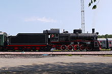


Драматическое увеличение стоимости дизельного топлива вызвало несколько инициатив для возрождения паровой энергии. [ 100 ] [ 101 ] Тем не менее, ни один из них не продвинулся до такой степени производства, и с начала 21 -го века локомотивы пара работают только в нескольких изолированных регионах мира и в туристических операциях.
Еще в 1975 году железнодорожные энтузиасты в Соединенном Королевстве начали строить новые паровые локомотивы. В том же году Тревор Барбер завершил свой 2 -футовый ( 610 мм ) локомотивная локомотива , которая проходила на железной дороге Meirion Mill . [ 102 ] Начиная с 1990-х годов число новых сборки, которые резко завершены, резко возросло с новыми локомотами, завершенными узкими калибрами Ffestiniog и Corris Railhays в Уэльсе. Компания Hunslet Engine была возрождена в 2005 году и начала строить паровые локомотивы на коммерческой основе. [ 103 ] Стандартный Lner Lner Peppercorn Pacific "торнадо" был завершен в Honpetown Works , Дарлингтон , и впервые пробежал 1 августа 2008 года. [ 104 ] [ 105 ] Он вступил в службу основной линии позже в 2008 году. [ 106 ] По состоянию на 2009 год [update] Более полдюжины проектов по созданию рабочих копий вымерших паровых двигателей продолжаются, во многих случаях используя существующие детали от других типов для их построения. Примеры включают BR 72010 Hengist , [ 107 ] BR Class 3MT № 82045, BR Class 2MT № 84030, [ 108 ] Брайтон Атлантический пляжный голова , [ 109 ] LMS 5551 Проект неизвестного воина , GWR " 47xx 4709, 2999 Lady of Lady of Lady of Lady of Lady of Lady of Gronge , 1014 County of Glamorgan и 6880 Betton Grange Projects. Эти новые проекты из Соединенного Королевства дополнительно дополняются новой сборкой Пенсильвании 5550 [ 110 ] Проект в Соединенных Штатах. Одна из целей группы состоит в том, чтобы превзойти рекорд скоростной скорости Steam Locomotive, удерживаемый 4468 крядом , когда 5550 завершен, и для 5550, чтобы заполнить огромный разрыв в сохранении парового локомотива.
В 1980 году американский финансист Росс Роуланд создал американские угольные предприятия для разработки модернизированного угольного парового локомотива. Его концепция ACE 3000 привлекла значительное внимание, но никогда не была построена. [ 111 ] [ 112 ]
В 1998 году в своей книге «Красная дьявола» и «Другие сказки с эпохи пар» , [ 113 ] Дэвид Вардейл выдвинул концепцию высокоскоростного высокоэффективного локомотива «Супер класс 5 4-6-0» для будущих паровых туристических поездов на британских основных линиях. Идея была формализована в 2001 году путем создания 5AT Project, посвященного разработке и построению 5AT Advanced Technology Steam Locomotive , но никогда не получала никакой крупной железнодорожной поддержки.
Места, где происходят новые сборки, включают: [ Цитация необходима ]
- GWR 1014 Округ Гламорган и GWR 2999 Lady of Lady of Lady of Lady of , оба построены в Железнодорожном центре Дидкот
- Муж 6880 Беттон Грандж , муж 4709 & LMS 5551 Неизвестный воин , все они построены на железной дороге Llangollen
- Lner 2007 Prince of Wales , Darlington Locomotive Works
- Lner 2001 Cock O 'The North, Doncaster
- Пенсильвания железная дорога 5550 , Поттстаун, Пенсильвания [ 110 ]
- BR 72010 Hengist , Великая центральная железная дорога
- BR 77021, TBA
- BR 82045, Железная дорога долины Северн
- BR 84030 & LBSCR 32424 Beachy Head, оба построены на железной дороге Блюбелл
- MS & LR/GCR 567, Руддингтон Великая Центральная железная дорога, Северная секция
- VR V499, Виктория, Австралия
В 2012 году Коалиция для устойчивой железной дороги [ 114 ] Проект был запущен в США с целью создания современного более скоростного парового локомотива, включающего улучшения, предложенные Ливио Данте Порта и других, и использование биомассы с твердым топливом. Топливо было недавно разработано Университетом Миннесоты Университета в сотрудничестве между Институтом окружающей среды (IONE) и устойчивым железнодорожным международным (SRI), организацией, созданной для изучения использования обороты Steam в современной железнодорожной установке. Группа получила последний выживший (но не бегающий) ATSF 3460 класса Steam Locomotive (№ 3463) через пожертвование от его предыдущего владельца в Канзасе, музее Великого оверленд. Они надеются использовать его в качестве платформы для разработки «самых чистых и мощных пассажирских локомотивов в мире», способного достигать скорости до 130 миль в час (210 км/ч). Названный «Проект 130», он направлен на то, чтобы побить мировую запись скорости парового поездка, установленную классом LNER A4 4468 Mallard в Великобритании со скоростью 126 миль в час (203 км/ч). Тем не менее, любая демонстрация претензий проекта еще предстоит увидеть.
В Германии небольшое количество бездомных паровых локомотивов все еще работают на промышленном обслуживании, например, на электростанциях, где на месте можно легко доступно запас Steam.
Небольшой городок Вольштин , Польша , примерно в 60 километрах (37 миль) от исторического города Познана , является последним местом в мире, где можно ездить на регулярно запланированном пассажирском поезде, притягнувшем от парового энергетики. Локомотив сарай в Wolsztyn - последний в своем роде в мире. Есть несколько рабочих локомотивов, которые ежедневно перевозит пригородные услуги между Wolsztyn, Poznan, Lezo и другими соседними городами. Можно принять участие в курсах с пейзажами через опыт Wolsztyn. В мире не осталось места, которое все еще работает ежедневно, не туристическую службу для пригородных/пассажирских пассажиров, отличных от Wolsztyn. Существует несколько лаковских локомотивов общего назначения OL49-класса 2-6-2 и один класс PT47 класса 2-8-2 в регулярном обслуживании. Каждый май Wolsztyn является местом фестиваля парового локомотива, который приносит посещающие локомотивы - часто более дюжины каждый год, все они работают. Эти операции не выполняются для туризма или музея/исторических целей; Это последняя линейка недизельной железной дороги на PKP (польская сеть штатов), которая была преобразована в дизельную питание.
Швейцарская компания Dampflokomotiv- und Maschinenfabrik DLM AG доставила восемь паровозок на железные дороги на стойках в Швейцарии и Австрии в период с 1992 по 1996 год. Четверо из них в настоящее время являются основной тягой на Бриенц Роторн-Бан ; Четверо других были построены для Шафбергбана в Австрии, где они управляют 90% поездов.
Та же самая компания также перестроила немецкий DR Class 52,80 2-10-0 локомотив до новых стандартов с такими модификациями, как роликовые подшипники, легкий масляный стрельба и изоляция котла. [ 115 ]
Изменение климата
[ редактировать ]Примеры и перспектива в этом разделе могут не представлять мировой взгляд на предмет . ( Февраль 2022 г. ) |
Будущее использование паровых локомотивов в Соединенном Королевстве вызывает сомнения из -за государственной политики в отношении изменения климата . Ассоциация железной дороги наследия работает с Всепартийной парламентской группой на Heritage Rail, чтобы продолжить управление паровыми локомотивами на угле. [ 116 ]
Многие туристические железные дороги используют нефтяные паровые локомотивы (или переоборудовали свои локомотивы для работы на нефти), чтобы уменьшить свой экологический центр, и поскольку мазут может быть легче получить, чем уголь правильного типа и размеры для локомотивов. Например, железная дорога Гранд -Каньон работает на своих паровых локомотивах на использованном растительном масле.
Организация под названием «Коалиция для устойчивой железной дороги» (CSR) разрабатывает экологически чистый угольный замену, сделанный из Torrefied биомассы . [ 117 ] В начале 2019 года они провели серию тестов с использованием железной дороги Эверетта для оценки эффективности биотоплива с положительными результатами. Было обнаружено, что биотопливо сжигает немного быстрее и горячее, чем уголь. [ 118 ] Целью проекта является в первую очередь на поиск устойчивого топлива для исторических паровых локомотивов на туристических железных дорогах, но CSR также предположил, что в будущем паровые локомотивы, приводимые в действие биомассы, могут быть экологически чистыми и экономически превосходными альтернативой дизельным локомотивам. [ 117 ] Кроме того, большой НДС, содержащий соль, может использоваться без необходимости пополнять среду. Большие нагревательные элементы были бы одним из методов пополнения системы, однако можно также накачать расплавленную соль, удаляя охлажденную соль и пополнение из объектов, которые содержат гораздо больший НДС. [ Цитация необходима ]
Паровые локомотивы в популярной культуре
[ редактировать ]Паровые локомотивы присутствовали в популярной культуре с 19 -го века. Народные песни того периода, в том числе « Я работал на железной дороге » и « Баллада Джона Генри » - это опора американской музыки и культуры.
Было сделано много паровых локомотивных игрушек, и железнодорожное моделирование - популярное хобби.
Паровые локомотивы часто изображаются в вымышленных работах, в частности, в серии железной дороги , проведенной Rev Wv Awdry , маленьким двигателем, который мог бы от Уотти Пайпер , Polar Express Крис Ван Аллсбург и Hogwarts Express из серии JK Rowling 's S Series. Они также были представлены во многих детских телевизионных шоу, таких как Thomas & Friends , основанные на персонажах из книг Awdry, и Ivor, который двигатель, созданный Оливером Постгейтом .
Hogwarts Express также появляется в серии фильмов о Гарри Поттере, изображенной GWR 4900 классом 5972 Олтон -Холл в специальной ливреи Хогвартса. Polar Express появляется в одноименном анимационном фильме .
Расширенная тематическая езда Funicular Hogwarts Express представлена в Universal Orlando Resort во Флориде, соединяющая участок Гарри Поттера Universal Studios с тематическим парком Islands of Adventure.
Полярный экспресс воссоздан на многих железных дорогах наследия в Соединенных Штатах, в том числе «Северный полюс Экспресс», вытянутый локомотивом Pere Marquette 1225 , который управляется Институтом железной дороги Steam в Оровассо, штат Мичиган . По словам автора Ван Аллсбурга, этот локомотив был вдохновением для истории, и он использовался в производстве фильма.
Ряд компьютерных и видеоигр оснащены локомотивами Steam. Железнодорожный магнат , выпущенный в 1990 году, был назван «Одна из лучших компьютерных игр года». [ Цитация необходима ]
Есть два примечательных примера паровых локомотивов, используемых в качестве зарядов на геральдических слоях оружия . Один из них - Дарлингтон , который отображает локомоцию № 1 . Другим является оригинальный швырки Swindon , не используемый в настоящее время, который отображает базовый паровой локомотив. [ 119 ] [ 120 ]

Паровые локомотивы - популярная тема для коллекционеров монет. [ Цитация необходима ] Серебряная 5 -песо Мексика 1950 года имеет паровой локомотив на обратном направлении в качестве выдающейся особенности.
20 евро Периодная монета с , измеряемая 11 июня 2003 года, показывает на лицевой стороне ранней модели парового локомотива ( Ajax ) на первой в Австрии железнодорожной линии Кайзера Фердинандс-Нордбан . Ajax все еще можно увидеть сегодня в музее Technisches Wien . В рамках программы 50 государственных кварталов квартал, представляющий штат Юта в США, изображает церемонию, где в 1869 году встретились две половинки первой трансконтинентальной железной дороги на вершине Pramontory. Монета воссоздает популярное изображение с церемонии с локомотивами Steam от каждого Компания сталкивается друг с другом, в то время как золотой всплеск движется.
Роман " Ночь на галактической железной дороге " [ 121 ] Кенджи Миядзава сосредоточен на идее парового поезда, путешествующего среди звезд. Роман Миядзавы позже вдохновил серию Лейджи Мацумото успешную " Galaxy Express 999 ".
Другая японская телевизионная франшиза, Super Sentai , представляет монстров на основе паровых локомотивов.
Зарядный человек, мастер робота из пятой части серии Mega Man , основан на паровом локомотиве.
Смотрите также
[ редактировать ]Общий
[ редактировать ]Типы паровозок
[ редактировать ]- Сформированный локомотив
- Кабина вперед локомотив
- Составной локомотив
- Дуплекс локомотив
- Электрический локомотив
- Руководитель парового локомотива
- Heilmann Locomotive
- Паровой локомотив высокого давления
- Паровые манекены и паровые трамваи
- Паровая турбинная локомотив
- Stripliner
- Танк -локомотив
- Триплекс локомотив
- Уайт
Примечания
[ редактировать ]- ^ Сопоставимые фигуры для последнего построенного британского грузового локомотива, класса 9F , составляли 139 длинных тонн (141 T ; 156 коротких тонн ) и 39 667 фунтов (176 450 н).
Ссылки
[ редактировать ]- ^ Фаулер, Джордж Литтл (1906). Локомотив Словарь; иллюстрированный словарный запас терминов, который обозначает американские железнодорожные локомотивы, их части, привязанности и детали строительства, с определениями и иллюстрациями типичной британской локомотивной практики; Пять тысяч сто сорок восемь иллюстраций . Нью -Йорк: Железнодорожный газетт . ISBN 978-0-912318-20-2 .
- ^ «Железные дороги» . Британская история онлайн .
- ^ Энтони Бертон (2000). Ричард Тревилик; Гигант пар . Aurum Press . С. 85–94. ISBN 1-85410-878-6 .
- ^ Jump up to: а беременный Гамильтон Эллис (1968). Изображенная энциклопедия железных дорог . Hamlyn Publishing Group . п. 20
- ^ Эллис, Гамильтон (1968). Изображенная энциклопедия железных дорог. С. 24–30. Hamlyn Publishing Group.
- ^ «Великолепный кряк: самый быстрый паровой локомотив в мире» . 17 февраля 2018 года.
- ^ Рид, Брайан (1972). Профиль Loco 24: Pennsylvania duplexii . Profile Publications Ltd.
- ^ Pennypacker, Bert (1962). Pennsy Power: паровые и электрические локомотивы Пенсильванской железной дороги, 1900-1957 . Элвин Стауфер.
- ^ «Высокая емкости локомотив для быстрого обслуживания» железнодорожный возраст. 106, № 25 . Симмонс-бордман издательская корпорация. 24 июня 1939 года.
- ^ М. Грант, Родерик (декабрь 1941 г.). «Поездка на Гаргантуа рельсов» . Популярная механика.
- ^ Кратвилл, Уильям (1972). Большой мальчик . Кратвилл Публикации.
- ^ «Бленкинсоп, Джон» . Оксфордский словарь национальной биографии (онлайн -ред.). Издательство Оксфордского университета. doi : 10.1093/ref: ODNB/2637 . ( Требуется членство в публичной библиотеке в Великобритании .)
- ^ Пэйтон, Филипп (2004). Оксфордский словарь национальной биографии . Издательство Оксфордского университета .
- ^ «Инженерные и железнодорожные работы» . Британская история онлайн .
- ^ Гордон, WJ (1910). Наши домашние железные дороги, том первый . Лондон: Frederick Warne & Co. С. 7–9.
- ^ Железнодорожный журнал , том 150, IPC Business Press, 2004, с. 11. Google Books.
- ^ Tzanakakis, Konstantinos (2013). Железнодорожная дорожка и его долгосрочное поведение: справочник по железнодорожной дорожке высокого качества . Springer Science+Business Media . ISBN 978-3-642-36051-0 - через Google Books.
- ^ Служба национальных парков . «Американские паровые локомотивы» . Получено 14 сентября 2021 года .
- ^ «Наследие Джона Фитча» . www.craven-hall.org . Архивировано из оригинала 31 октября 2020 года . Получено 24 февраля 2016 года .
- ^ Йетман, Дэвид С. (2010). Без опоры . Dog Sear Publishing. ISBN 978-1-60844-475-5 - через Google Books.
- ^ Фрэнсис Тревилик (1872). Жизнь Ричарда Тревитка: С учетом его изобретений, том 1 . E. & F.N.Spon.
- ^ «Паровой локомотив Ричарда Тревитика | Рагор» . Museumwales.ac.uk. Архивировано из оригинала 15 апреля 2011 года . Получено 3 ноября 2009 года .
- ^ «Годовщина парового поезда начинается» . Би -би -си . 21 февраля 2004 г. Получено 13 июня 2009 года .
Город Южного Уэльса начал месяцы празднования, чтобы отметить 200 -летие изобретения парового локомотива. Merthyr Tydfil был местом, где 21 февраля 1804 года Ричард Тревитик взял мир в эпоху железной дороги, когда он установил один из своих паровых двигателей на местном железном мастере
- ^ Пэйтон, Филипп (2004). Оксфордский словарь национальной биографии . Издательство Оксфордского университета.
- ^ Гарнетт, AF (2005). Стальные колеса . Cannwood Press. С. 18–19.
- ^ Янг, Роберт (2000) [1923]. Тимоти Хакворт и локомотив (переиздание изд.). Льюз, Великобритания: Гильдия книг.
- ^ Jump up to: а беременный Гамильтон Эллис (1968). Изображенная энциклопедия железных дорог . Хэмлин издательская группа. С. 24–30.
- ^ «Изобретатель Джона Стивенса» .
- ^ Стовер, Джон Ф. (1987). История железной дороги Балтимора и Огайо . West Lafayette, In: Purdue University Press . С. 35–36. ISBN 0-911198-81-4 .
- ^ « Dewitt Clinton» локомотив » . Американские рельсы . 2020 . Получено 2 марта 2020 года .
- ^ «Джон Булл локомотив» . Национальный музей американской истории . Смитсоновский институт . 2021 . Получено 30 марта 2021 года .
- ^ "Джон Булл" . Железнодорожный музей Пенсильвании . 2021. Архивировано из оригинала 29 апреля 2021 года . Получено 30 марта 2021 года .
- ^ «Overland Locomotive: проблемы с подачей воды» . Аргус . 21 марта 1927 года . Получено 11 марта 2014 года .
- ^ Хилтон, Джон (1986). «Паровые локомотивные котлы». Задний путь . № (Специальный вступительный вопрос). Атлантические транспортные издатели. С. XL - XLI. ISSN 0955-5382 . OCLC 226007088 .
- ^ Ароны. Британский паровой железнодорожный локомотив с 1825 по 1925 год . Тол. 1
- ^ См. Раздел статьи класса A1/A3 класса LNER о резком увеличении доступности, вызванного в этом отношении путем применения выхлопа KylChap к Gresley Pacifics в начале 1960 -х годов
- ^ Jjg Koopmans: огонь горит намного лучше ... nl-venray 2006, ISBN 90-6464-01-0
- ^ Как действительно работают паровые локомотивы, PWB Semmens и AJ Goldfinch, Oxford University Press 2000, ISBN 0-19-856536-4 , P. 172
- ^ "La Locomotive A Vapeur", Андре Шапелон, английский перевод Джорджа У. Карпентера, Camden Miniature Steam Services 2000, ISBN 0-9536523-0-0 , рис. 37
- ^ Уайт, Джон Х. младший (1997). Американские локомотивы, инженерная история 1830–1880, пересмотренное и расширенное издание . Балтимор, доктор медицинских наук: издательство Университета Джона Хопкинса . п. 85. ISBN 0-8018-5714-7 .
- ^ «Швейцарские электрические локомотивы» . 7 января 2010 года. Архивировано с оригинала 18 октября 2010 года . Получено 12 ноября 2015 года .
- ^ "Западное побережье и R711" . Группа новостей : AUS.Rail .
- ^ Jump up to: а беременный в дюймовый и Swengel, Frank M. (1967). American Steam Locomotive, Vol. 1, эволюция парового локомотива . Давенпорт, Айова: ПУБЛИКАЦИЯ СМИ МЕДЛАСТА.
- ^ «Лечение порта» . www.portatratement.com . Архивировано с оригинала 7 января 2014 года.
- ^ « Коалиция для устойчивой железной дороги » . Архивировано из оригинала 5 апреля 2013 года.
- ^ «NPS.gov Home страница (Служба национальных парков США)» . www.nps.gov . Получено 17 ноября 2020 года .
- ^ Робинсон, Джалин. «Паровой двигатель должен вернуться на железные дороги Гранд -Каньон» . Tripsavvy . Получено 14 июля 2022 года .
- ^ «Экскурсия Гранд -Каньон с отличием поздних поездов» . Поезда . 26 апреля 2022 года . Получено 14 июля 2022 года .
- ^ «История - Sugar Express» . 25 октября 2020 года. Архивировано с оригинала 25 октября 2020 года . Получено 19 сентября 2022 года .
- ^ «Возьмите вегетарианскую поездку в Гранд-Каньон» . Мужской журнал . 2 апреля 2021 года . Получено 14 июля 2022 года .
- ^ Кокран, Джейсон (2 февраля 2009 г.). «Поезда Диснейленда экономит деньги, переключившись на использованную французскую нефть» . Аол Архивировано из оригинала 18 января 2017 года . Получено 18 января 2017 года .
- ^ «Железная дорога Гранд -Каньон получает награду по культуре и консервации» . 15 августа 2017 года.
- ^ «Задержка - определение» . Oxford English Dictionares Online, издательство Оксфордского университета, март 2018 г., www.oed.com/view/entry/105090. Архивировано из оригинала 29 мая 2018 года . Получено 29 мая 2018 года .
- ^ "Лаг, Н.2". OED онлайн. Март 2018 года. Издательство Оксфордского университета. http://www.oed.com/view/entry/105062 . Доступ 22 мая 2018 года.
- ^ Скотт, Рон; GN Large Atlantics (Profile Publications Berks UK - без даты), с. 129
- ^ Jump up to: а беременный в дюймовый и фон Белл, Мортон (1950). Локомотивы (седьмое изд.). Лондон: Vitue & Co Ltd.
- ^ Уайт, Джон Х. младший (1968). История американского локомотива, его развитие: 1830–1880 ((Перепечатка: Dover Publications, New York 1979) изд.). Балтимор, MD: Johns Hopkins Press. С. 146–149.
- ^ Jump up to: а беременный в Снелл, Джон Б. (1971). Машиностроение: железные дороги . Лондон: Лонгман.
- ^ Белый 1968 , с. 114–124
- ^ BTC Справочник 1957 , с. 40
- ^ Холлингсворт, Брайан; Кук, Артур (1987). Великая книга поездов . Лондон: Саламандре книги. п. 192.
- ^ "Cass City Chronicle" (PDF) . Cass City Chronicle : 3. 29 июля 1938 года. Архивировано из оригинала (PDF) 26 сентября 2007 года . Получено 26 сентября 2007 года .
- ^ Циклопедия инженерии, том III, редактор Луи Дерр, Американское техническое общество Чикаго 1919, с. 224
- ^ Ролт, LTC (1976). Красный для опасности: история железнодорожных аварий и железнодорожных безопасности (3 -е изд.). Ньютон Эббот: Дэвид и Чарльз. п. 33. ISBN 978-0-7153-7292-0 .
- ^ Ниньо, Эмануэль (1997). Промышленная смазка . Манила, Филиппины: Рекс. п. 46. ISBN 978-971-23-2178-8 .
- ^ Ригг, Артур (1878). Практический трактат на паровом двигателе . Лондон: Спон. OCLC 1251342932 .
- ^ Справочник по железнодорожным паровым двигателям . Лондон: Британская транспортная комиссия . 1957. С. 126–127. OCLC 4431123 .
- ^ «Январь - декабрь 1953; первое издание». Железнодорожный журнал . 99 Лондон: Международная печатная компания : 287. 1953. Asin b00uo1jlyg .
- ^ BTC Справочник 1957 , с. 53
- ^ «Отчет о несчастном случае в 1955 году» (PDF) .
- ^ Оксфордский английский словарь : бафф 1
- ^ «Глоссарий терминов и определений» , доступ к 21 февраля 2012 г.
- ^ «Закон о железнодорожном регулировании 1842 года» . Британская база данных законодательства . 30 июля 1842 года . Получено 5 марта 2012 года .
- ^ Уайт, Джон Х. младший (1997). Американские локомотивы, инженерная история 1830–1880, пересмотренное и расширенное издание . Балтимор, MD: Johns Hopkins Press. С. 213–214. ISBN 0-8018-5714-7 .
- ^ «Паровой локомотив в Америке, его развитие в двадцатом веке», Альфред В. Брюс, First Edition, Ww Norton & Company, Inc 1952, с. 262
- ^ Доминик Уэллс (2015). Как работает паровой локомотив: новое руководство (в твердом переплете изд.).
- ^ Rails» «Steam по-прежнему управляет популярной наукой , декабрь 1937 года, рисуя с. 32–33 на многоцилиндрах
- ^ Ван Римсдийк, Джон Т. (1994). Составные локомотивы, международное исследование . Пенрин, Англия: Атлантическая транспортная издательство. ISBN 0-906899-61-3 .
- ^ Дэвид Росс, The Steam Locomotive: история , Tempus Publishing, Gloucestershire, 2006, ISBN 0-7524-3916-2
- ^ «Электрические локомотивы Швейцарии» . Архивировано из оригинала 18 октября 2010 года . Получено 14 сентября 2010 года .
- ^ Общество LNWR. "LNWR Locomative Classe" . Lnwrs.org.uk. Архивировано из оригинала 2 декабря 2008 года . Получено 3 ноября 2009 года .
- ^ «Словарь шотландцев» . Dsl.ac.uk. Архивировано из оригинала 20 февраля 2008 года . Получено 3 ноября 2009 года .
- ^ Адамс, Генри (1908). Справочник инженера Касселла . Лондон: Касселл и компания. п. 389.
- ^ Аллен, Сесил Дж. (1949). Локомотивная практика и производительность в двадцатом веке . Кембридж, Англия: W Heffer and Sons Ltd.
- ^ Аронс, Эл (1987) [1927]. Британский паровой железнодорожный локомотив 1825–1925 . Лондон: Bracken Books. п. 123. ISBN 1-85170-103-6 .
- ^ «Учебное поведение в стале - Лондон Мидленд и шотландская железная дорога» на YouTube
- ^ Британские железные дороги «Последняя паровочная железнодорожная газетта» 23 марта 1960 г. с. 355
- ^ «Пенсильвания железнодорожная локомотивная классификация @ wall2.com» . Все2.com. 2 февраля 2003 г. Получено 3 ноября 2009 года .
- ^ Совершенствование американского парового локомотива , Дж. Паркер Лэмб, издательство Индианы Университет, 2003, ISBN 0-253-34219-8 , P. 135
- ^ Статья о магазинах PRR Altoona «где 14 000 труд» Марка Смита, Мишель Жиру и Джея Уильямса, журнала по сохранению локомотива и железной дороги, июль - август 1987, ISSN 0891-7647
- ^ Broggie 2014 , стр. 25-26.
- ^ Оберг, Леон (1975). Локомотивы Австралии . Ах и Ау Рид. ISBN 978-0-589-07173-8 .
- ^ Jump up to: а беременный Гунцбург, Адриан (1984). История паровых локомотивов WAGR . Австралийское железнодорожное историческое общество (Западная Австралийская дивизия), Перт. ISBN 978-0-589-07173-8 .
- ^ Мейклехон, Бернард (январь 1906 г.). «Новые двигатели на железных дорогах: электрические и бензиновые автомобили, заменяющие паровой локомотив» . Работа мира: история нашего времени . XIII : 8437–8454 . Получено 10 июля 2009 г.
- ^ «Конструкция и производительность, полученная из нефтяного двигателя» .
- ^ "Пересмотр локомотива" на YouTube
- ^ «Висконизин DNR - карбонатная химия» (PDF) . Архивировано из оригинала (PDF) 12 июля 2017 года . Получено 4 ноября 2015 года .
- ^ "Очистка и осмотр локомотива" на YouTube
- ^ Руководство по сцеплению дизельного топлива для инженеров . Британская транспортная комиссия. 1962. С. 15–16.
- ^ «Проект 5AT по разработке современного парового локомотива для британских железных дорог» . Архивировано из оригинала 15 августа 2012 года . Получено 6 ноября 2006 года .
- ^ «Расширение железной дороги на Андах: реактивация и модернизация существующего флота 75-сантиметрового калибра 2-10-2 паровых локомотивов» . Архивировано из оригинала 28 сентября 2007 года.
- ^ Куайн, Дэн (ноябрь 2016 г.). «Трикси и железная дорога Meirion Mill». Узкий мир .
- ^ Персонал. «О Ханслете Steam Co» . Hunslet Hunslet Engine Company . Получено 4 августа 2008 года .
- ^ Робертс, Дэвид (3 августа 2008 г.). «Недавно построенный Steam Loco выходит на дорожки» . Darlington & Stockton Times . Получено 4 августа 2008 года . [ Постоянная мертвая ссылка ]
- ^ Персонал (22 сентября 2008 г.). «60163 Торнадо в пути» . Би -би -си тройники . Получено 1 октября 2008 года .
- ^ Glance, Джонатан (2 августа 2008 г.). «Новый паровой локомотив обнародован» . Хранитель . Лондон Получено 4 августа 2008 года .
- ^ «Официальный сайт Хенгиста» . 72010-hengist.org . Получено 3 ноября 2009 года .
- ^ «Страница 84030 на веб -сайте Bluebell Railway» . Bluebell-railway.co.uk. 14 апреля 2008 г. Получено 3 ноября 2009 года .
- ^ «Секция Beachy Head на веб -сайте Bluebell Railway» . Блюбелл Железная дорога . Получено 3 ноября 2009 года .
- ^ Jump up to: а беременный «Раздел часто задаваемых вопросов - доверие T1» . Пенсильванская железная дорога T1 Steam Locomotive Trust. 2016. Архивировано с оригинала 24 августа 2019 года . Получено 23 апреля 2017 года .
- ^ "Ultimate Steam Page" . TrainWeb.org . Получено 3 ноября 2009 года .
- ^ «Американские угольные предприятия - Ace3000 и др.» . Martynbane.co.uk . Получено 3 ноября 2009 года .
- ^ Вардейл, Дэвид (1998). Красный дьявол и другие сказки с эпохи пара . Опубликовано автором. ISBN 0-9529998-0-3 Полем Архивировано из оригинала 6 февраля 2010 года.
- ^ "Дом" . Коалиция для устойчивой железной дороги .
- ^ «Справочная работа DLM AG 2-10-0 локомотив 52 8055» . Архивировано из оригинала 18 марта 2009 года . Получено 8 июня 2009 года .
- ^ «Паровые линии сталкиваются с двойной угрозой при подавлении сжигания угля» . 9 августа 2019 года.
- ^ Jump up to: а беременный «Торрефированная биомасса» .
- ^ «Тестирование железной дороги Эветт» .
- ^ "Дарлингтонский герб" . Вестника мира . Получено 10 июня 2018 года .
- ^ "Swindon Caing" . Вестника мира . Получено 10 июня 2018 года .
- ^ «Сто японских книг для детей (1946–1979)» . Международный институт детской литературы, Осака . Получено 7 февраля 2007 года .
Библиография
[ редактировать ]- Брогги, Майкл (2014). Железнодорожная история Уолта Диснея: мелкое увлечение, которое привело к полномасштабному королевству (4-е изд.). Издатели для надевания компании . ISBN 978-1-57864-914-3 .
Дальнейшее чтение
[ редактировать ]- GA Nokes , Эволюция парового локомотива (с 1803 по 1898 год) , (Лондон: Железнодорожная издательская компания, 1899)
- CE Wolff, Modern Locomative Practice: трактат по проектированию, строительству и работе паровых локомотивов (Манчестер, Англия, 1903)
- Генри Гринли, модель локомотива (Нью -Йорк, 1905)
- Гр Хендерсон, Стоимость локомотива (Нью -Йорк, 1906)
- Мы Далби, экономичная работа локомотивов (Лондон, 1906)
- Ай Тейлор, современные британские локомотивы (Нью -Йорк, 1907)
- Эль -Аронс, Развитие британского локомотивного дизайна (Лондон, 1914)
- Эль -Аронс, Строительство и техническое обслуживание парового двигателя (Лондон, 1921)
- JF Gairns, локомотивное соединение и перегрев (Philadelphia, 1907)
- Ангус Синклер, Разработка двигателя локомотива (Нью -Йорк, 1907)
- Вон Пендред, железнодорожный локомотив, что это такое и почему это так (Лондон, 1908)
- Брозиус и Кох, школа лидера локомотива (Тринадцатое издание, три тома, Wiesbaden, 1909–1914)
- Гл Фаулер, Локомотивные сбои, чрезвычайные ситуации и их средства правовой защиты (Седьмое издание, Нью -Йорк, 1911)
- Фишер и Уильямс, Pocket Edition of Locomative Engineering (Chicago, 1911)
- Ta Annis, современные локомотивы (Adrian Michigan, 1912)
- Ce Allen, Modern Locomotive (Кембридж, Англия, 1912)
- WG Knight, Практические вопросы о работе локомотива (Boston, 1913)
- Гр Хендерсон, Недавнее развитие локомотива (Филадельфия, 1913)
- Райт и Свифт (редакторы) Локомотивный словарь (Третье издание, Филадельфия, 1913)
- Робертс и Смит, практическая работа локомотива (Филадельфия, 1913)
- Э. Протеро, Железные дороги мира (Нью -Йорк, 1914)
- М.М. Киркман , локомотив (Чикаго, 1914)
- Кл Дикерсон, локомотив и вещи, которые вы должны знать об этом (Клинтон, Иллинойс, 1914)
- PWB Semmens, AJ Goldfinch, как на самом деле работают паровые локомотивы (Oxford University Press, US, 2004) ISBN 0-19-860782-2
- Джеральд А. Ди, пожизненная железнодорожная фотография в профиле фотографа , Публикации поезда, Студфилд, 1998. (Австралийский пар)
- Swengel, FM American Steam Locomotive; Тол. 1. Эволюция американского парового локомотива , Публикация Midwest Rail, Айова, 1967.
- Раков В.А. Локомотивы отечественных железных дорог 1845–1955 Транспорт, Москва, 1995
(Rakov Va Locomotives of Thatelady Railways гг 1845–1955 . - JJG Koopmans: Огонь горит намного лучше ... nl-venray 2006, ISBN 90-6464-01-0